DIY Guides, Howto & Guides
Updating the Firmware on the GamesCare SCART Switch
This tutorial will show you how to update the firmware on a GamesCare 8 in 2 out Smart SCART Switch. If your switch is running firmare 2.0 or higher, you do not need to follow this tutorial and you can instead update the firmware using the online update option by connecting the switch to the internet.
 Warning! Incorrectly flashing your GamesCare product can result in it becoming inoperable. Please proceed at your own risk. Errors or malfunctions caused by incorrectly flashing the firmware are not covered under warranty. If in doubt, please use our GamesCare Switch update service here, where we will upgrade the switches audio performance and install the new firmware for you.
Soldering skills are required in order to install the required header for the programmer. If you are not confident with a soldering iron it is highly recommended that you send your switch in for servicing/updating instead.
Prerequisites
In order to complete this tutorial, you will require the following things.
- FT232RL USB TO TTL 3.3V/5V FTDI Serial Adapter Module (available e.g on AliExpress)
- 6 Position Header Connector (for example, this one from DigiKey)
- Soldering iron and workstation
- Windows PC (it may be possible to use Linux or Mac but only Windows is covered in this tutorial, sorry!)
Adding the programming header
Dismantle your GamesCare SCART switch by unscrewing the screws on the top of the unit. Keep a note of where each part goes, since you will need to follow this process in reverse to reassemble the unit once firmware flashing is complete.
Solder the 6 position header to the bottom left of the SCART switch PCB, directly to the left of the reset button. Check your work for shorts, particularly make sure not to short pin 4 (VCC or voltage) with any other pin.
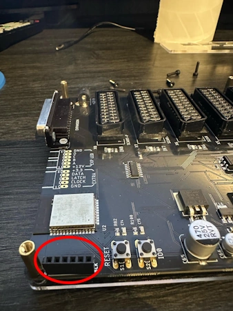
It is strongly recommended that you do NOT skip this step. Without the header installed, the programmer may not make proper contact with the PCB. This can result in the flash process failing part way through, rendering the switch inoperable.
Setting up the programmer
Configure your FT232RL programmer to 3.3 volt mode by moving the jumper so that it is set between the middle pin and the right pin.
Connect the FT232RL to your Windows PC using a mini-USB to USB-A cable. A small red light should illuminate on the programmer.
Determining the correct COM port
Since your PC may have one or more COM ports already in use, it is necessary to use Device Manager to determine the correct COM port number.
First, open Device Manager on your PC, by searching for “Device Manager” on the Windows search bar, or by navigating to Windows control panel. Administrator access is not required since we are not changing any settings, so any warnings about this can safely be ignored.
With Device Manager open, search in the list for “Ports (COM & LPT)” and expand it.
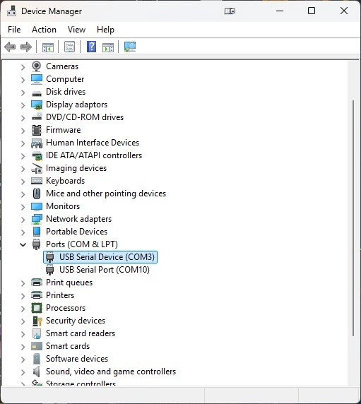
Just as in the example above, you may see several different entries under “Ports (COM & LPT)”. Double click on each one until you find one that matches the picture below.
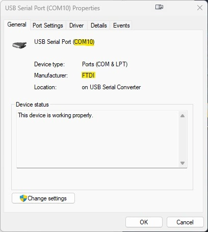
Note the COM port number (in this example, COM10) and then close the properties window.
Extracting the firmware files
Download the zip file here and extract it to the root of your C:\ folder. If you want to use another location on your PC then note that you will have to manually fix the file paths yourself within the flash download tool.
Open the “gcfw” folder on your C:\ drive and start the “flash_download_tool_3.9.7” program by double clicking on it. The window shown below should then appear.
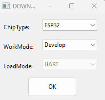
Ensure your options are set the same as in the example (“ChipType ESP32”, “WorkMode – Develop”) and then click “OK”. The following window will then appear.
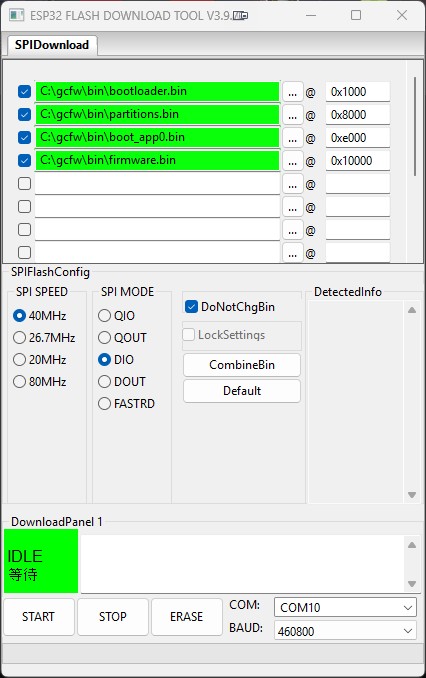
Set all the options as per the screenshot above. Make sure the hex numbers on the right match with the ones in the sceenshot too. If you didn’t extract to the root of your C: drive, use the “…” button to correct the paths to the firmware files.
At the bottom right of the window, check that “COM:” is pointing to the correct COM port. This is the port value that you determined previously, and may be different to the one shown in the example.
Connecting the programmer
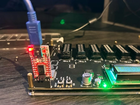
Connect the programmer to the pin header you soldered onto the board. The programmer should face outwards with the LEDs clearly visible. Once connected, power on the GamesCare switch.
With the programmer now connected to both your PC and the GamesCare switch, and with the GamesCare switch powered on, click on the “START” button at the bottom left of the ESP32 Flash window.
On your PCs screen you should notice a black command prompt window, it usually appears under the ESP32 Flash window. Move this window so it is visible and you should see the following text, followed by a string of full stops that keeps growing.
test offset : 4096 0x1000
case ok
test offset : 32768 0x8000
case ok
test offset : 57344 0xe000
case ok
test offset : 65536 0x10000
case ok
..............................
Press and hold both the RESET and IO0 buttons on the GamesCare switch for around 10 seconds, then release them. Programming should then commence, if it does not, try holding the buttons again. You might need to try several times, but eventually it should work and you will see the following text appear.
Uploading stub...
Running stub...
Stub running...
Changing baud rate to 460800
Changed.
NO XMC flash detected!
FLASH_CRYPT_CNT 0
ABS_DONE_0 False
Compressed 17536 bytes to 12202...
Compressed 3072 bytes to 129...
Compressed 8192 bytes to 47...
Compressed 1230688 bytes to 844653...

is stub and send flash finish
Congratulations, you have now updated the firmware on the GamesCare switch. Power off the switch, remove the programmer and reassemble the case and the process is finished. Future firmware updates can now be applied automatically by simply using the firmware download option on the switches menu (Wi-Fi and internet connection is required).
Entire possible that it’s an unrelated issue, but I updated mine to 2.1 and it worked fine for a week or so, but now only inputs 1-4 are working, and cycling to inputs 5 through 8 causes it to just drop back and cycle through inputs 1-4 again. IC6 is getting _very_ hot which may be related, so it may just be a coincidental component failure.
Please remove this. It looks like it was a failed 4HC4051D IC, I removed it and the immediate switching problem instantly went away. Have ordered some good quality replacements and will see how that goes, although I’m measuring 8V to the IC and the rated max for it is 7V, so there may be other issues.