CPS2 build not flashing
- This topic has 28 replies, 3 voices, and was last updated July 17, 2025 at 10:59 AM by
.
- You must be logged in to reply to this topic.
NewHome › Forums › CPS2 digital AV interface › CPS2 build not flashing
<p style=”text-align: right;”>Hi all. I built myself a CPS2 for my MV1C but I cannot seem to flash it. Everything looks fine and it’s not neatest jobs but any ideas. 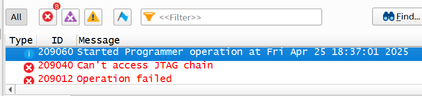 </p>
</p>
Assuming you have working programmer and drivers, that kind of issue indicates FPGA doesn’t get power or some of the JTAG pins is not properly soldered.
Yeah my programmer works fine as flashed OSSC fine. I will go over all soldered parts and try again thanks.
I have reseated everything and reflowed the board but still the same error. I originally installed the CPS2 onto my MV1C board to flash it but D1 started to smoke. Could I have fried the FPGA chip? 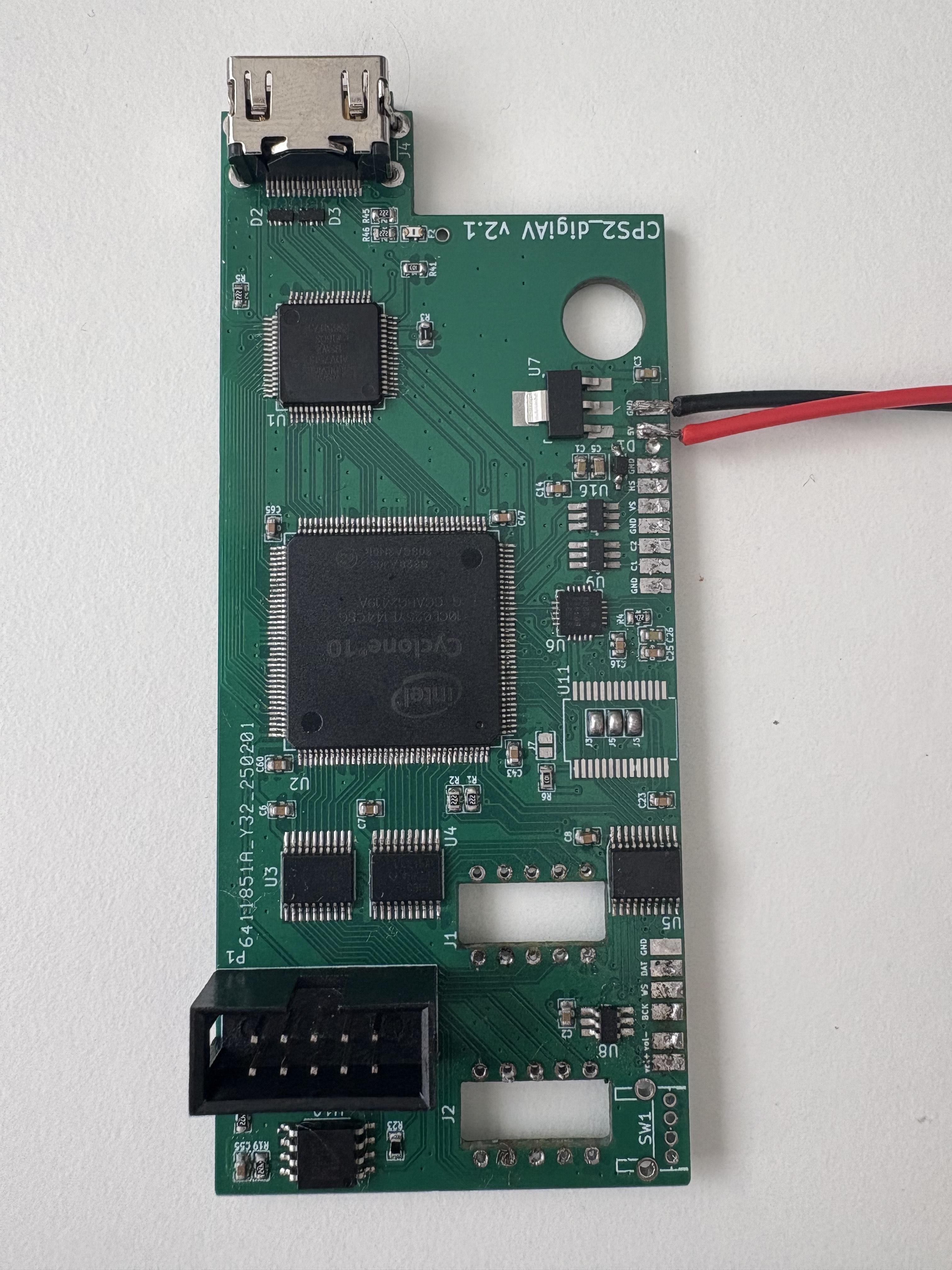
You should first check the output voltages of relevant regulators (U7, U12-14). Regarding D1, it could start smoking if it’s installed wrong way or overvoltage / reverse voltage is applied to 5V input. You should remove this protection diode as it has probably been damaged and could cause issues.
I have replaced D1 and made sure it is the correct way round. I will test the regulators thanks.
U7 outputs 3.30v
U12 outputs 1.19v
U13 outputs 2.48v
U14 outputs 1.20v
U15 outputs 1.79v
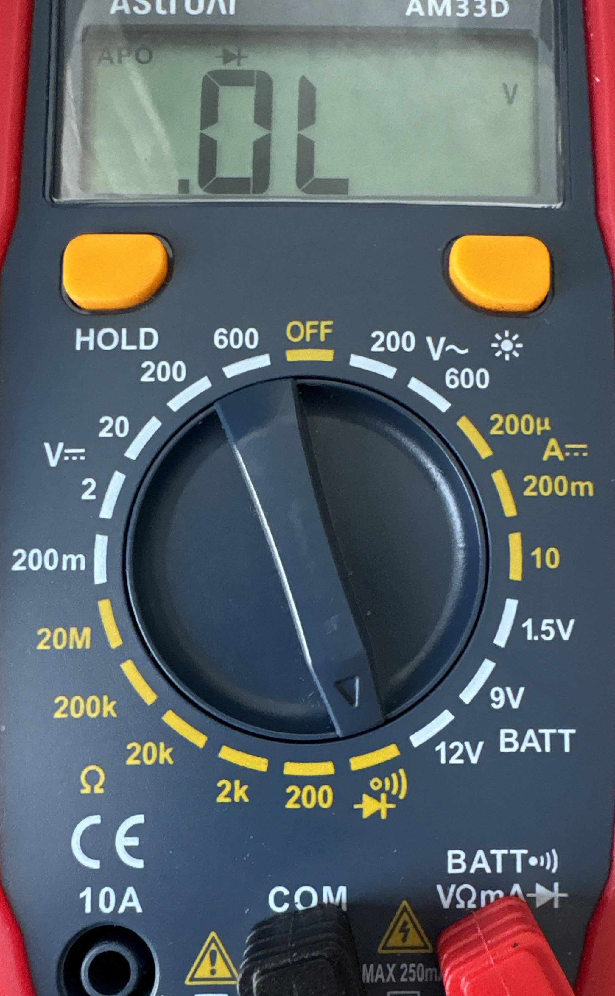
Those looks correct. I’d test next connectivity of JTAG pins (TCK, TMS, TDI, TDO) via diode tester while power is disconnected (red lead to GND and black lead to those pins on JTAG header – you should get a reading around 0.5-0.7V on each).
Ok. thanks for all your help so far. Will try that next. Hope we can get this working.
I have the multimeter set to continuity like below.
Then with the red lead on point 1 in the picture I put the black pin on points 2-5. Results are below. Something is wrong 🙂
2 TDI – 0v
3 TMS – 0v
4 TDO – 0v
5 TCK – 0.912
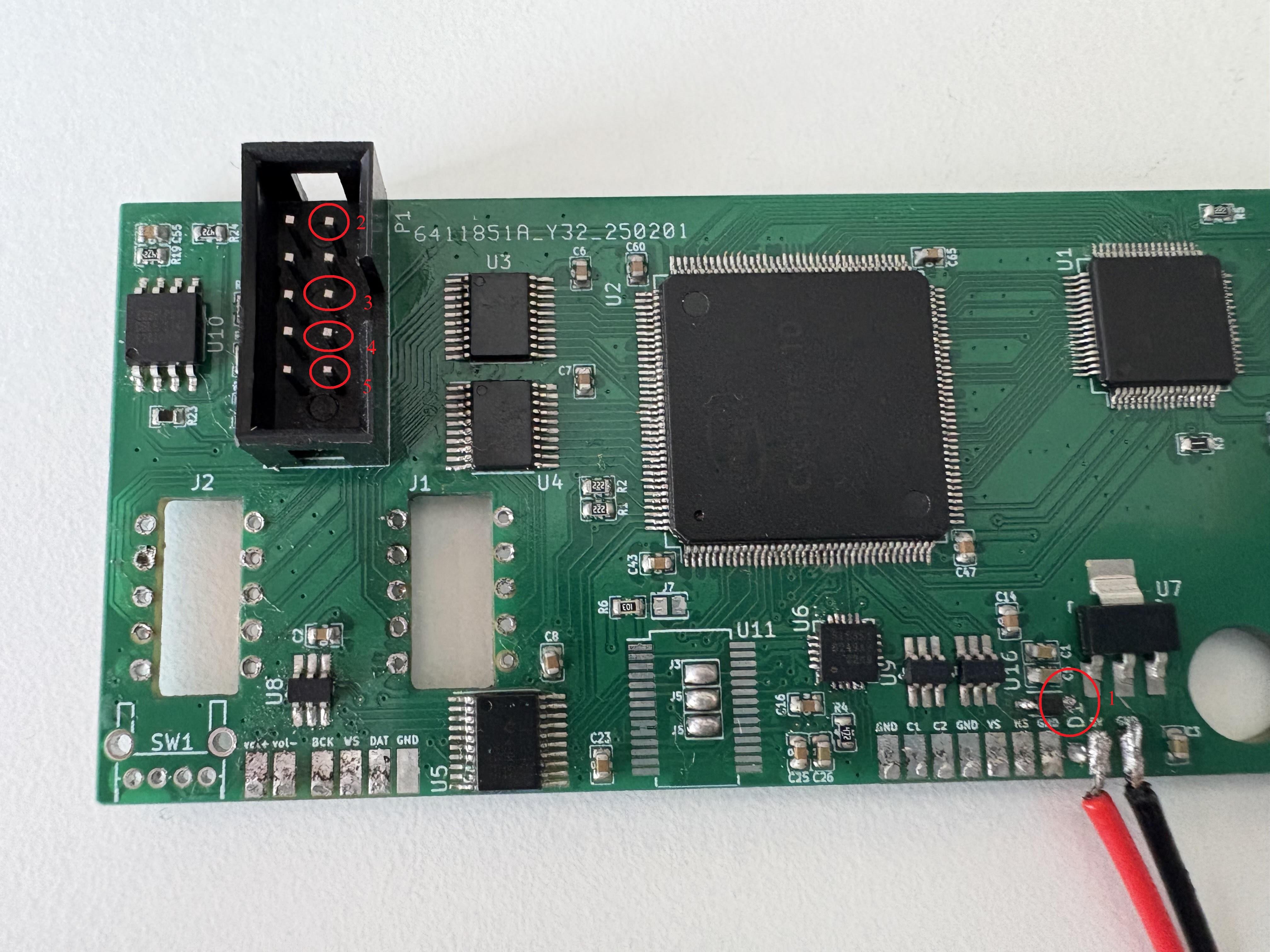
Your point 1 is 5V, not GND. Connect the lead on the other side of the diode.
2 – .472
3 – .949
4 – .490
5 – .353
TMS looks unusually high but otherwise I don’t see anything wrong. Is the FPGA from a trusted vendor?
Got it from mouser
| Cookie | Duration | Description |
|---|---|---|
| _gat | 1 minute | This cookie is installed by Google Universal Analytics to restrain request rate and thus limit the collection of data on high traffic sites. |
| Cookie | Duration | Description |
|---|---|---|
| __gads | 1 year 24 days | The __gads cookie, set by Google, is stored under DoubleClick domain and tracks the number of times users see an advert, measures the success of the campaign and calculates its revenue. This cookie can only be read from the domain they are set on and will not track any data while browsing through other sites. |
| _ga | 2 years | The _ga cookie, installed by Google Analytics, calculates visitor, session and campaign data and also keeps track of site usage for the site's analytics report. The cookie stores information anonymously and assigns a randomly generated number to recognize unique visitors. |
| _gid | 1 day | Installed by Google Analytics, _gid cookie stores information on how visitors use a website, while also creating an analytics report of the website's performance. Some of the data that are collected include the number of visitors, their source, and the pages they visit anonymously. |
| Cookie | Duration | Description |
|---|---|---|
| IDE | 1 year 24 days | Google DoubleClick IDE cookies are used to store information about how the user uses the website to present them with relevant ads and according to the user profile. |
| test_cookie | 15 minutes | The test_cookie is set by doubleclick.net and is used to determine if the user's browser supports cookies. |
| Cookie | Duration | Description |
|---|---|---|
| ct_checked_emails | session | No description |
| ct_has_scrolled | session | No description |
| ct_mouse_moved | session | No description |
| ct_screen_info | session | No description |
| wordpress_apbct_antibot | session | No description |
| wp_woocommerce_session_9cc3598a6315be16da4f85bb374cf6a5 | 2 days | No description |