No Sync Intellivision
NewHome › Forums › OSSC, OSSC Pro and DExx-vd isl › OSSC – Discussion and support › No Sync Intellivision
- This topic has 43 replies, 8 voices, and was last updated September 14, 2020 at 11:34 PM by
niugnep.
-
AuthorPosts
-
November 12, 2017 at 3:55 AM #17092
Does OSSC need status RGB signal (pin 16) in order to work with AV1/RGBS selected?
I have Intellivision with RGB connected to XRGB2. It displays fine on Sony TV.
I switch to my Euro SCART cable and connect it to OSSC and OSSC says no sync. Same Euro SCART cable works with my Odyssey 2 console, so not sure what the problem is.
November 12, 2017 at 11:49 AM #17096No OSSC doesn’t need that pin connected. Those consoles definitely outputting RGB? (I guess yes since you said you had them working on an XRGB2 as well, but doesn’t hurt to check).
November 16, 2017 at 9:45 PM #17250Yes, Intellivision is outputting RGB using RGB mod board. It syncs using Sony PVM or XRGB2, just not OSSC. Let know what to do. I have scope if needed.
November 17, 2017 at 12:24 PM #17267Did you try adjusting Hsync tolerance under Sync opt.?
November 18, 2017 at 1:29 AM #17293Yes, just tried tonight. Same result. Anything else to try?
November 26, 2017 at 8:14 AM #17547I have this same issue. My OSSC will not sync to my RGB modded Intellivision (AV1) but my Intellivision works fine on my xRGB-mini. I have upgraded to 0.79a. How would I know what to set the many menu Sync options to for the Intellivision? Any ideas?
November 28, 2017 at 12:00 AM #17602@grips03 if you have a scope, could you probe sync output of the mod board and take a capture of vsync (typically 3 scanlines) and some lines before and after it? You could also try increasing HPLL pre and post coast to 3 or 4 in sync menu to see if it helps.
November 29, 2017 at 7:09 PM #17662I tried HPLL pre and post coast at 3 and 4. Still no sync.
I can take picture of sync signal. Is there a certain spot to take picture of? I have Rigol 1102E.
November 30, 2017 at 12:57 AM #17668Just use pulse trigger with “wider than” function on the negative pulse to lock to vsync.
December 14, 2017 at 12:59 AM #17991Below is a picture of my RGB modded Intellivision’s sync pulse on my ancient oscilloscope.
I set the scope so that the vertical was .5v per CM (between each line) and 0 volts was at the bottom
Here is a picture of the calibration on the scope:

Then I set the time (horizontal) to 5 uS while looking at sync signal:

I am not an expert on video so please let me know what else it would make sense to look at.
Thanks!
December 20, 2017 at 4:26 AM #18070Anyone?
December 20, 2017 at 7:57 PM #18078Your capture looks like horizontal sync signal. I assume that sync line is unloaded as it shows around 3.3Vpp. It’d help if you can redo the measurement with 75ohm load, preferably capturing vblank portion of the composite sync (like here) if possible.
January 27, 2018 at 11:12 PM #18784I am using the board referenced in the article at:
My board is this one:

I am using the “R”, “G”, and “B” lines of the outputs (for RGB, of course) as well as the second “G” (ground) and the “S” line which is the line showing the sync pulse I posted earlier. I have tried using the “V” output as sync but nothing will work then. Also, I have never been able to find any relevant signal being produced from the “V” output. I initially assumed this was composite video out and attempted to use that output for sync to my xRGBmini (pin 3 of the xRGB input port) but it did not work. The “S” line produces an excellent image. Perhaps I am doing something fundamentally wrong. I do not know how to get the signal you are asking me to take an image of. From where should I take the reading? I do not know where to get “composite sync” from the board I have.
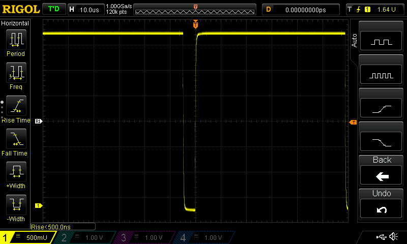
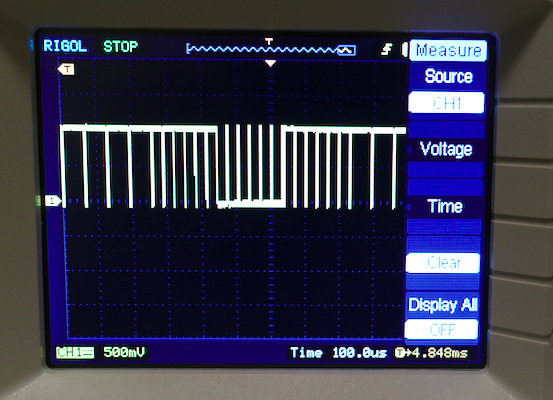
January 29, 2018 at 5:13 AM #18798connect scope to S.
January 29, 2018 at 5:44 AM #18800Yes, that is what I posted earlier images from, the “S” output. Here are two more images taken with my new scope from the “S” output (still no load):

-
AuthorPosts
- You must be logged in to reply to this topic.