OSSC Pro AV3 HV sync fix for Splitfire, X68k etc.
NewHome › Forums › OSSC, OSSC Pro and DExx-vd isl › OSSC – Discussion and support › OSSC Pro AV3 HV sync fix for Splitfire, X68k etc.
- This topic has 6 replies, 3 voices, and was last updated April 6, 2024 at 6:53 PM by
djpsykom1.
-
AuthorPosts
-
March 24, 2024 at 6:52 PM #60879
Some users have encountered stability issues with TTL sync (HV or c-sync) with certain sources. Splitfire and X68k (except XVI compact) have been identified so far. I’ve looked into the issue using a sync buffer similar than in Splitfire and have managed to replicate it and make a hardware fix. The root cause seems to be the PLL in ADC chip constantly losing horizontal lock with these specific sources. Why that happens is still a mystery, but below is background for the issue and a method/mod to fix it.
The digital IOs in the chip are 3.3V as in most chips made in 90s or later. A level shifting circuit is required from TTL sync inputs which are usually 5V, and the datasheet recommends using a basic resistor divider with capacitor on parallel to make transition time faster:

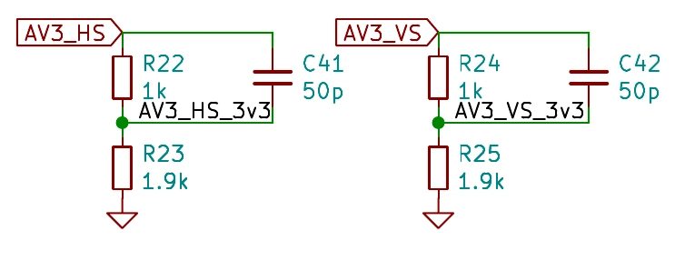
A simple resistor divider with low resistances would not have major filtering effect, but would instead load unnecessarily the source (especially bad as many are high-impedance). However, while the capacitor reduces low-pass filtering, it also causes over & undershoot during the transitions which can result to noise on the supply if voltage goes beyond pad protection diode limits (~0.7V above VDDIO and below GND). Anyway, the recommended circuit (shown above) was used as it had worked on the tested sources. The chip datasheet also claims HSYNC slicer should be very tolerant againts any noise in the sync signal:
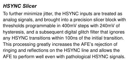
However, in practice this doesn’t seem to hold. Changing slicer threshold (which is really nice feature considering different source levels before and after divider) does not solve the issue and PLL loses lock more or less often. Removing the parallel capacitors and/or changing divider resistor values did not result to fully stable sync either. As last resort, I replaced the recommended level conversion circuit with a SN74LVC2G17 buffer IC (which is how this is handled on OSSC Classic). While on paper this is inferior solution as sync threshold becomes fixed as set in the buffer IC, this seemed to remove all unstability in my test setup. A nice thing about the buffer is that while it’s 3.3V chip, it tolerates 5V inputs so source HV sync can be connected to it directly, resulting to minimal loading effect to the source. Below is short guide how to install the chip on OSSC Pro board. It’s not particulary hard mod but involves desoldering 0402 parts. As some people have damaged OSSC Classics doing another sync mod involving removal of 0603 resisor, I can’t recommend this for people doing SMD work the first time.
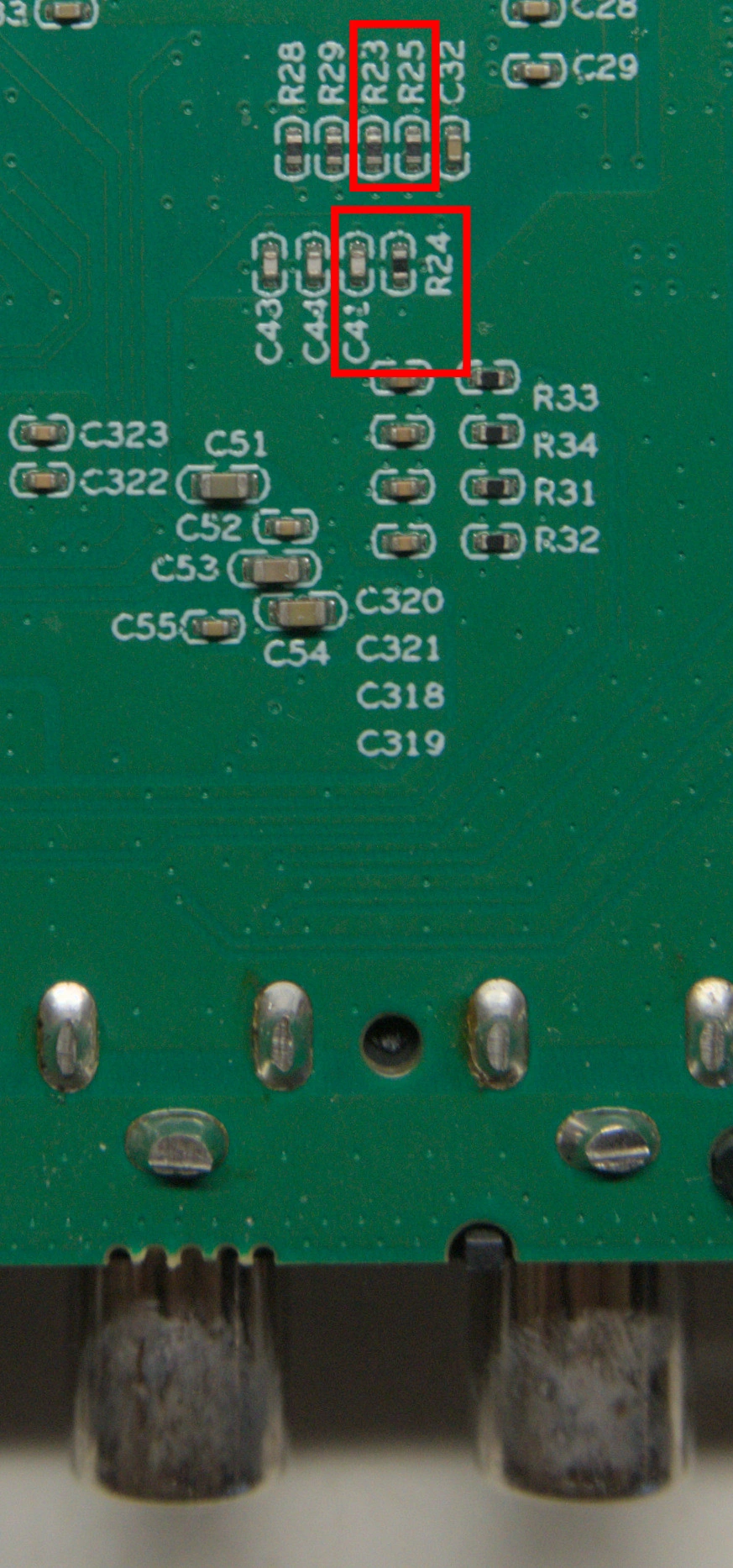
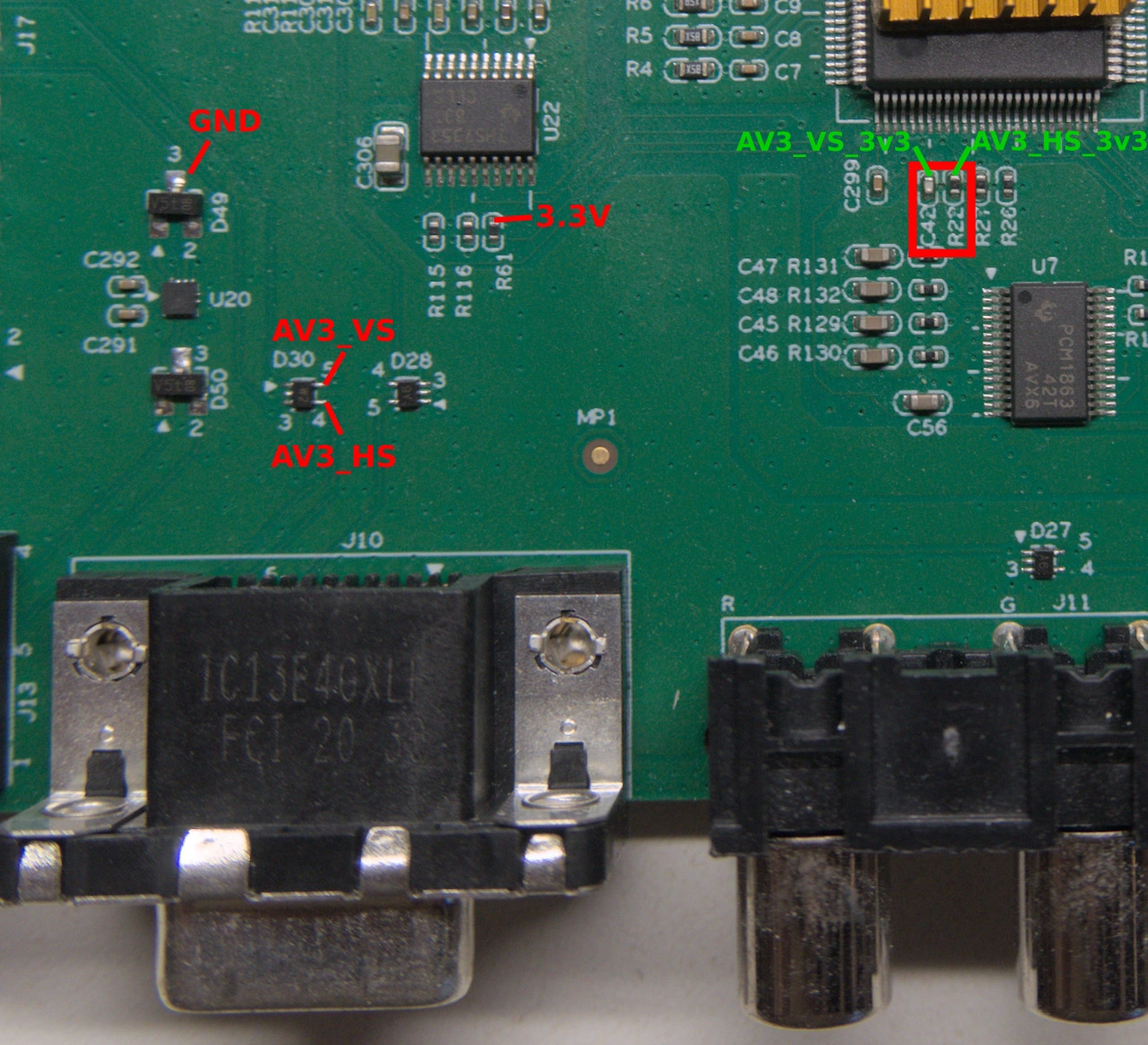
As the first step, the mod requires removal of R22-25 and C41-42. These 6 parts are highlighted by red rectangles on the 2 images below. Add first a small blob of new solder of both ends of these SMD parts, and then another blob on the end of soldering iron (set to ~330C). Then just bridge the part with the iron and gently push/pull it away with tweezers etc. If you do use force, you’re doing it wrong and risk damaging the board.
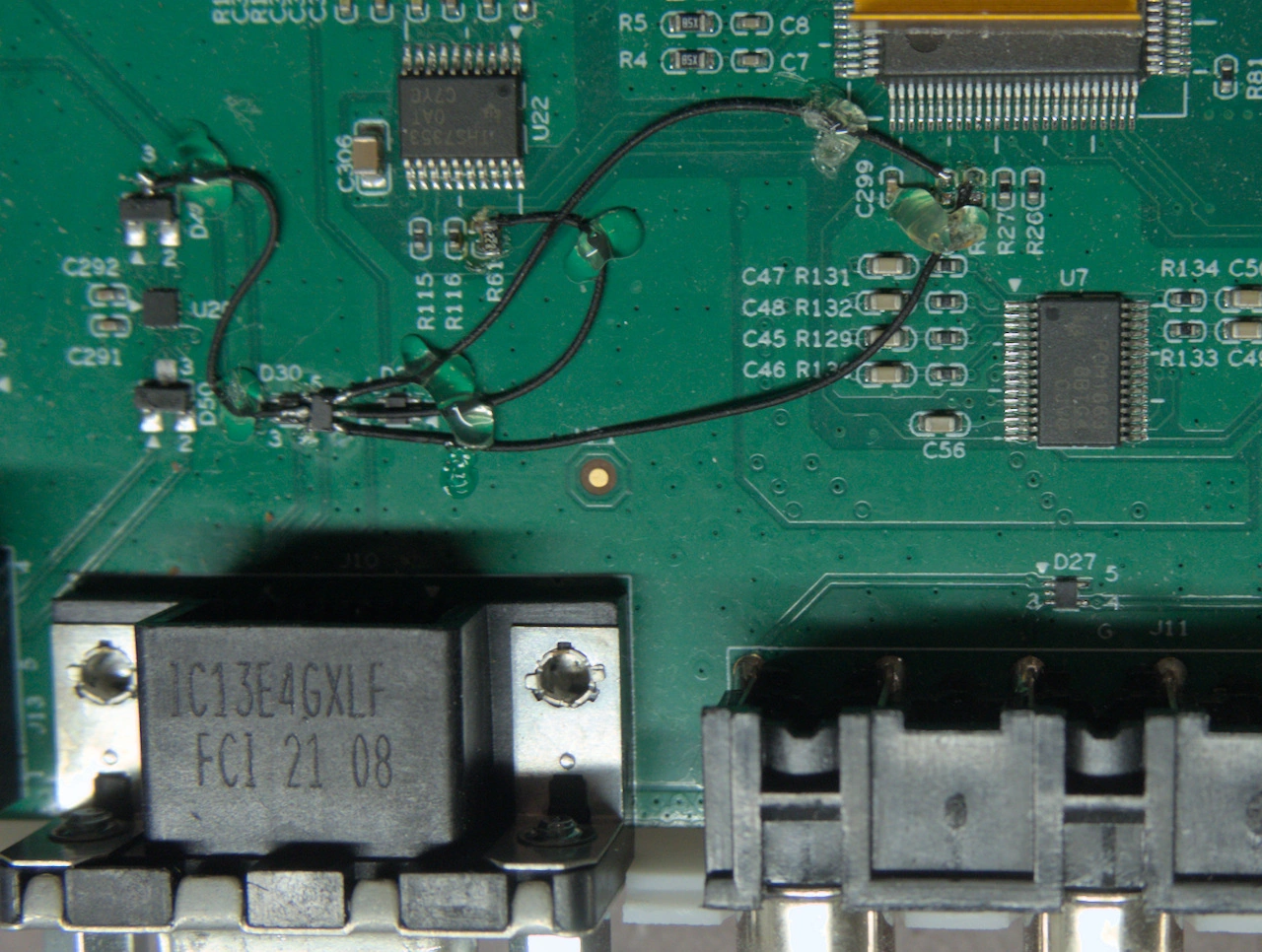
Once the parts are removed, it’s time to place SN74LVC2G17 on the board. It is possible to buy SN74LVC2G17 in SOT23 (“DBV”) or smaller SC70 (“DCK”) package which have identical pinouts as shown below. One can select it according to preference & soldering experience. This guide uses SC70 variant.

The A inputs are connected to AV3_VS/HS points and Y outputs to AV3_VS_3v3/HS_3v3 points. Vcc and GND are soldered to nearest supply points (3.3V and GND) as highlighted in above image. Before gluing the chip to the board, it’s best to solder wires to its pins, especially if using SC70. On the other hand, SC70 can be soldered directly into D30, reducing required wire count to 4. After soldering, test continuity and make sure nothing is shorted on the supplies. It’s good practice to glue the wires into the PCB in the end.
 March 24, 2024 at 6:57 PM #60880
Sorry for the linked images not showing currently. The forum seems to enforce https:// links.
March 25, 2024 at 4:28 PM #60926Thanks Markus! Images have now been copied to the websites own hosting to prevent the security warning.
March 25, 2024 at 5:59 PM #60934Looking at the PCB and the fix just to realize I don’t have the fine tools to get this accomplished.
Is there a way I could ship my OSSCP back to you fine folks to sort this out?
Thank you for finding out what needs to be done to get this working with a Splitfire.
March 25, 2024 at 5:59 PM #60935.
-
This reply was modified 1 year, 4 months ago by
djpsykom1. Reason: Double post
March 27, 2024 at 9:56 AM #60972I could certainly ask BetaGamma if they’re willing to do it.
April 6, 2024 at 6:53 PM #61138How can I get a hold of @betagamma
Thank you
-
This reply was modified 1 year, 4 months ago by
-
AuthorPosts
- You must be logged in to reply to this topic.

