NewHome › Forums › Repairs and Upgrades › Philips CDi 470 RGB mod
Tagged: Composite pic looks okay, RGB too bright
Thank you very much for your help, I hope this will do the trick
I’m sorry I have to ask again, but just to be sure: are you referring to this part on your github-page:”Built-in RGB Enable pad. No more soldering in a pull-up resistor.”?
Of course I mean this part, please forget the upper posting:”470 (Tested Working. Requires Solder Jumper to Left.)”
<p style=”text-align: left;”>Of course I mean this part, please forget the upper posting:”470 (Tested Working. Requires Solder Jumper to Left.)”</p>
Also about your second hint:”They also don’t need to solder the RGB enable pad because they moved the resistor on the mainboard” does this mean we don’t have to do part 4 of your instructions, because we did part 5, removing the 3171 resistor? Sorry that we need to ask so often, but this seems to be trickier than expected. Thank you for your help
Back again, still not done. Our assumption is that we have to remove the resistor from pin 13, this might activate RGB. Anyone can confirm this?
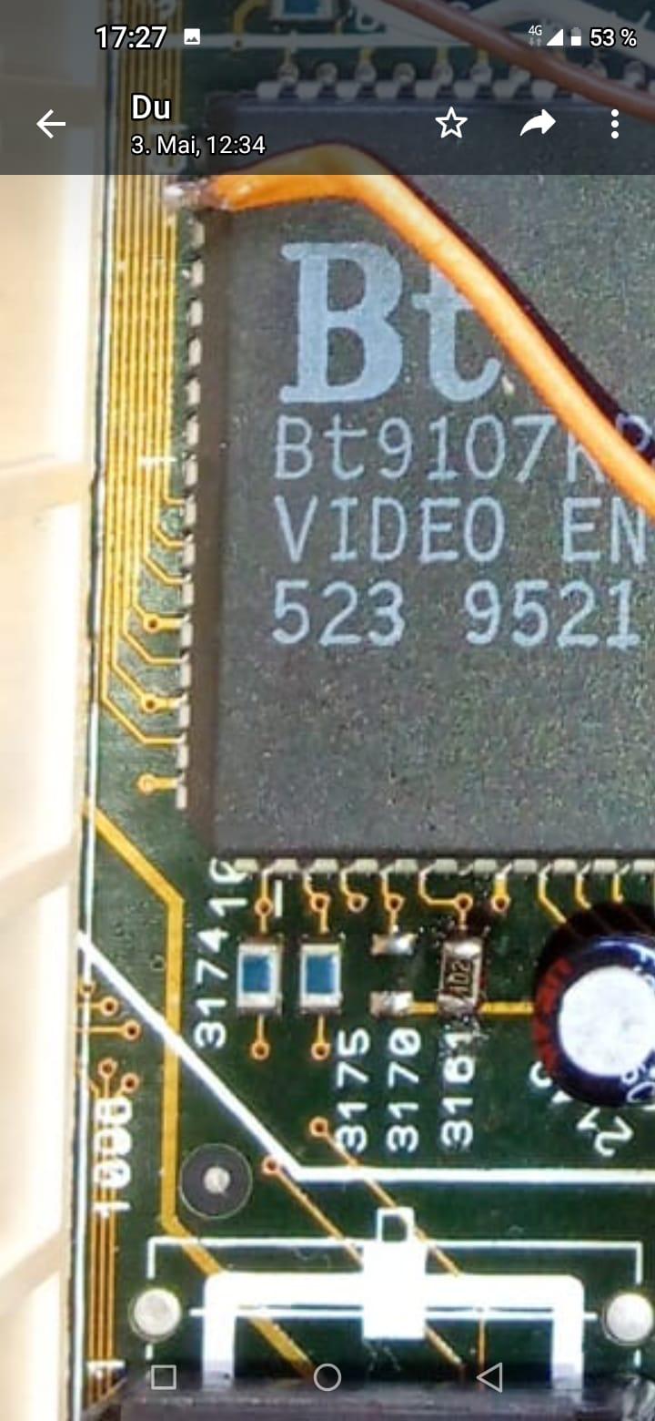
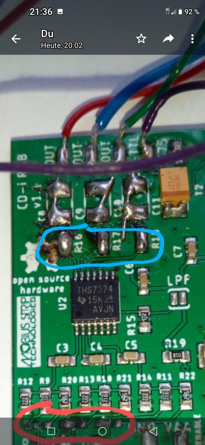
About the last pic I posted: here the resistor is set on 3161 which should activate RGB. 3170 is composite video, this resistor is on the back side on mass flow/minus but it could also be done on the front side on Plus. Any idea which one is the correct one? Thank you!
I’ll see if I can get Chris’ attention again!
“You should remove any wire you may have soldered to pin 13, but leave the resistor you soldered at 3161.
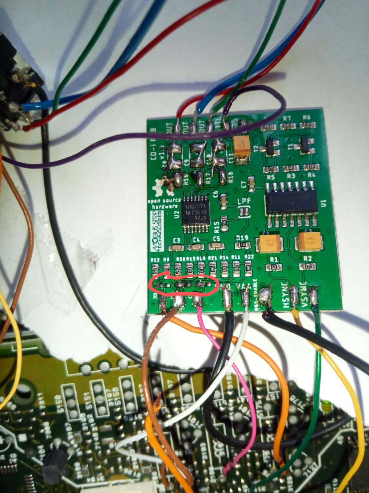
Then make sure that you solder the jumpers to the left for RGB signals”
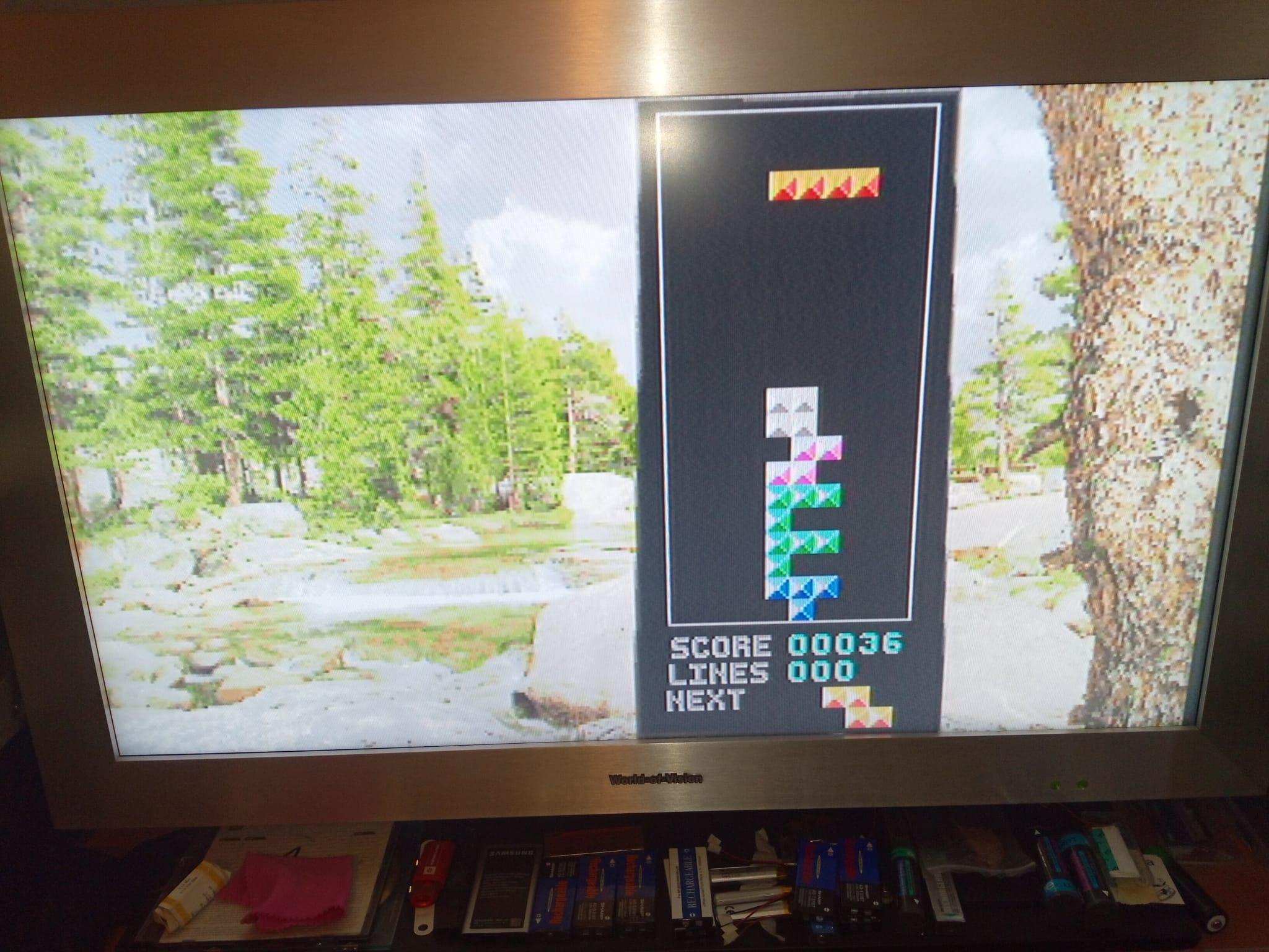
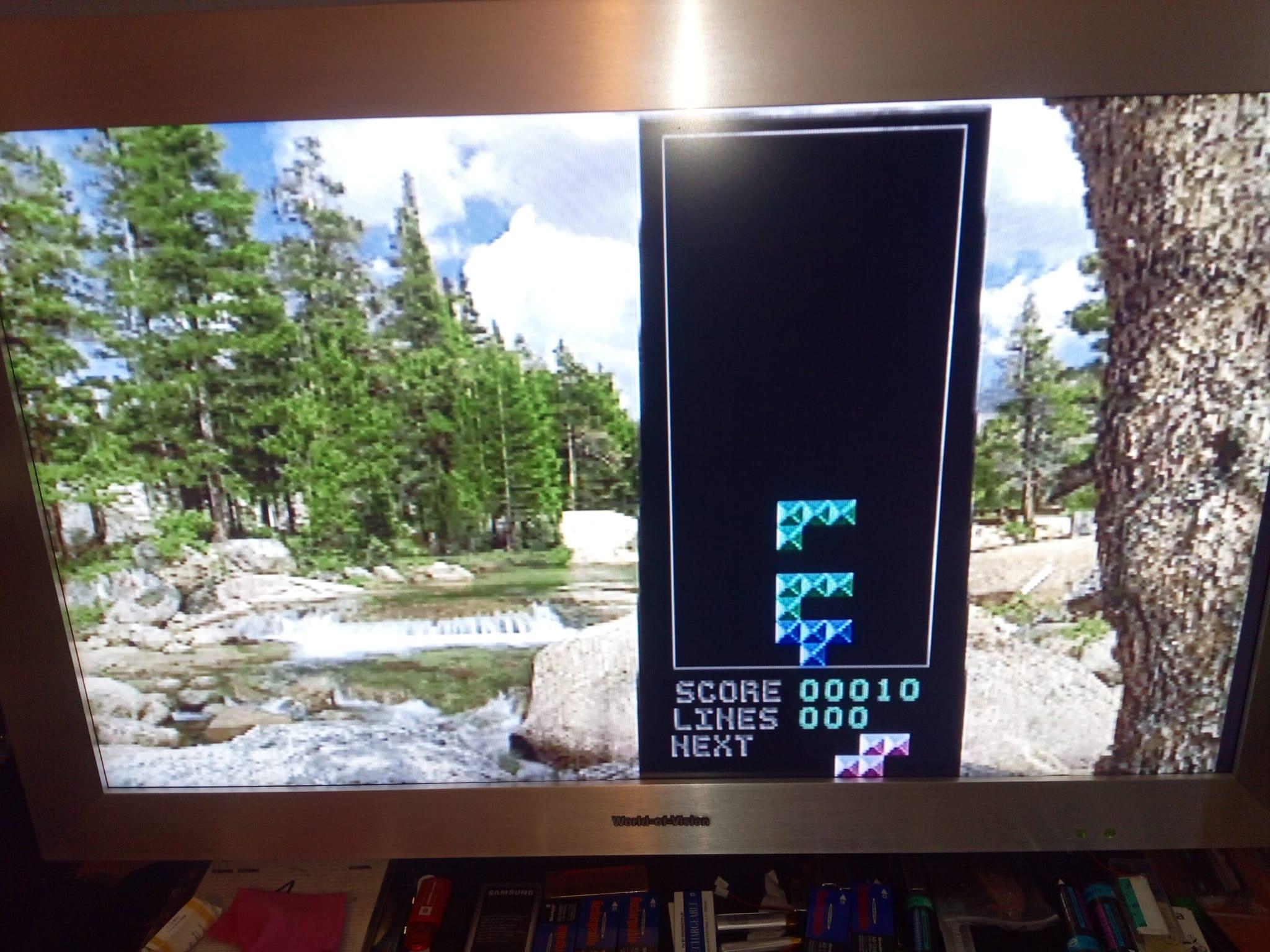
Thank you for your help, it’s working! Mostly. All jumpers are left now, but is it normal that conposite is still working? Also, the image is too bright, see the pics below. Any final clues to solve this would be very welcome. Thank you!
| Cookie | Duration | Description |
|---|---|---|
| _gat | 1 minute | This cookie is installed by Google Universal Analytics to restrain request rate and thus limit the collection of data on high traffic sites. |
| Cookie | Duration | Description |
|---|---|---|
| __gads | 1 year 24 days | The __gads cookie, set by Google, is stored under DoubleClick domain and tracks the number of times users see an advert, measures the success of the campaign and calculates its revenue. This cookie can only be read from the domain they are set on and will not track any data while browsing through other sites. |
| _ga | 2 years | The _ga cookie, installed by Google Analytics, calculates visitor, session and campaign data and also keeps track of site usage for the site's analytics report. The cookie stores information anonymously and assigns a randomly generated number to recognize unique visitors. |
| _gid | 1 day | Installed by Google Analytics, _gid cookie stores information on how visitors use a website, while also creating an analytics report of the website's performance. Some of the data that are collected include the number of visitors, their source, and the pages they visit anonymously. |
| Cookie | Duration | Description |
|---|---|---|
| IDE | 1 year 24 days | Google DoubleClick IDE cookies are used to store information about how the user uses the website to present them with relevant ads and according to the user profile. |
| test_cookie | 15 minutes | The test_cookie is set by doubleclick.net and is used to determine if the user's browser supports cookies. |
| Cookie | Duration | Description |
|---|---|---|
| ct_checked_emails | session | No description |
| ct_has_scrolled | session | No description |
| ct_mouse_moved | session | No description |
| ct_screen_info | session | No description |
| wordpress_apbct_antibot | session | No description |
| wp_woocommerce_session_9cc3598a6315be16da4f85bb374cf6a5 | 2 days | No description |