Super hot U5 and no leds ON on OSSC 1.6
NewHome › Forums › OSSC, OSSC Pro and DExx-vd isl › OSSC – Discussion and support › Super hot U5 and no leds ON on OSSC 1.6
- This topic has 13 replies, 2 voices, and was last updated March 9, 2024 at 7:56 PM by
Morpheus_79.
-
AuthorPosts
-
February 24, 2024 at 8:38 PM #60280
Hi everyone,
My first post here 🙂 So, here’s my story: I let my OSSC powered on by mistake during 2 or 3 days. After that, it gave no signs of life anymore. LEDs off, no LCD display or HDMI output.
I googled a bit and found that the ‘usual suspects’ in this case are fuse F1 and diode D5. F1 visually seemed OK, but I shortened it. I also removed D5. Still the same results : no signs of life at all from my dear OSSC.
I then noticed that U5 was extremely hot (I almost burnt my fingertip on it), after only 1s of power ON.
What would you recommend me to do ? Do you think that U5 is broken (or is the very high temperature normal ?). Replacing U5 seems a bit tricky without desoldering the LCD and other parts. Should my OSSC power ON or give signs of life with D5 removed ?
Any hints are welcome. This OSSC was the main part of my vintage gaming room, I’d by very sad to loose it !
February 25, 2024 at 2:42 AM #60282The OSSC should work without D5… but removing D5 and shorting the fuse isn’t a good idea, because:
D5 is TVS diode that clamps voltage to 5V (in reality effective clamping voltage is a bit higher and depends on current), protecting from surges and overvoltage. When continuous overvoltage (or negative voltage with more than ~0.6V amplitude) is applied, it burns into a short circuit so that downstream devices are still protected. That eventually triggers overcurrent protection (e.g. fuse) if such is present. The diode and fuse are placed before power switch, so if you hadn’t power turned on yet, then you almost certainly did not damage anything but the diode.
If one or both are broken, than it’s for a reason. Circumventing both may damage your OSSC further.
If U5 gets very hot, you should check for shorts like described here:
https://github.com/marqs85/ossc_pcb/blob/v1.6/assembly/assembly_tips.txt
It’s a good idea to check that power supply lines are not shorted to ground. It can be done easiest by checking all the regulators:
-on bottom side, there are 8 small regulators in SOT-23-5 packages (U6, U7 etc.). Verify with a continuity meter that only the middle pin on the side with 3 legs is connected to ground
-on top side, there is one larger regulator (U5) behind the display. Verify that only the middle pin (on the side with 3 pins) and the heatsink pin are connected to GNDFebruary 25, 2024 at 10:21 AM #60283Thanks Morpheus_79 for the help. I checked the regulators : U5 has two pins connected to GND (the middle one plus another one), and most of the bottom side regulators also the two pins connected to ground (also the middle one plus another one).
Do you think that this short circuit is internal to a regulator (and that I should try to replace it), or might it be located elsewhere ?
I also noticed that my U5 has no heatsink, and that it gets burning hot. Could it be that letting the OSSC ON during several days without heating caused some melting or short inside it ?
-
This reply was modified 1 year, 7 months ago by
Louthrax.
February 26, 2024 at 4:55 AM #60293I also noticed that my U5 has no heatsink, and that it gets burning hot. Could it be that letting the OSSC ON during several days without heating caused some melting or short inside it ?
U5 doesn’t need a heatsink and shouldn’t get extremely hot. While it’s probably not recommended to run the OSSC for days and days and days, there should nothing get “melted” together or fail because of extreme heat produced. The A/D converter IC (U1) is the only one getting pretty hot – therefore its heatsink.
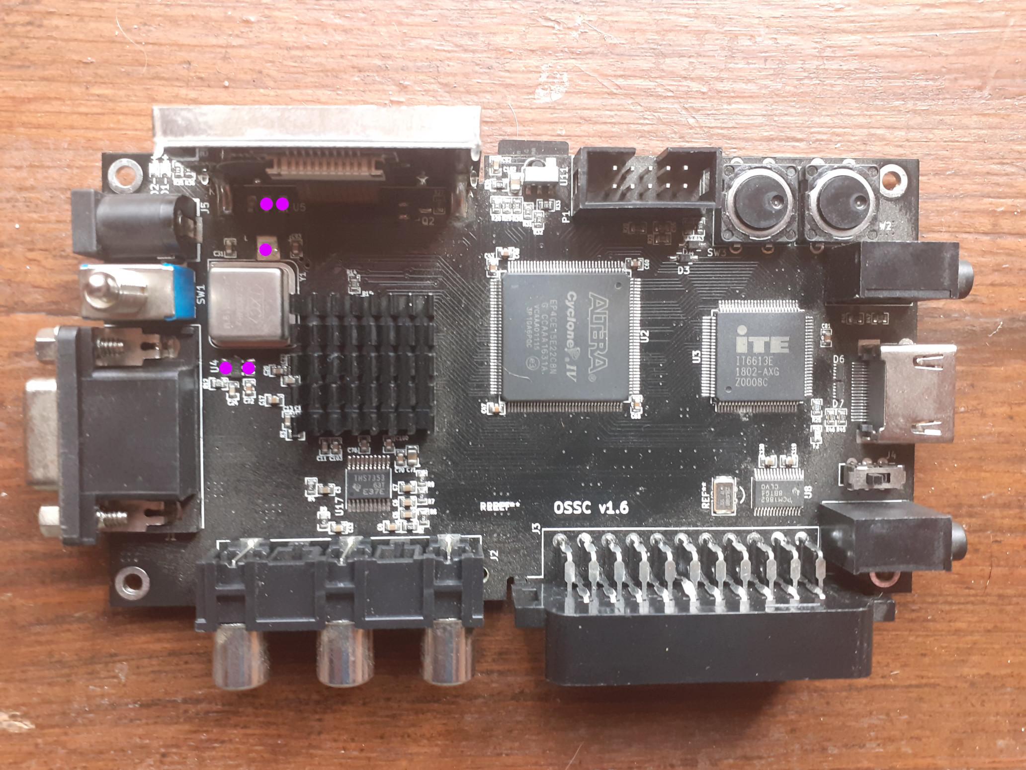
More detailed informations are needed. On U5: the big pin on one side and the middle pin on the side with the three pins are connected to ground? Is that correct??
Which regulators on the bottom side of the pcb have a short to ground (U?)? Please take a photo and mark their pins connected to ground!
Do you think that this short circuit is internal to a regulator (and that I should try to replace it), or might it be located elsewhere ?
For each regulator the input and output are each connected with a capacitor, which is connected to ground. So it could be a failed capacitor… or the regulator itself.
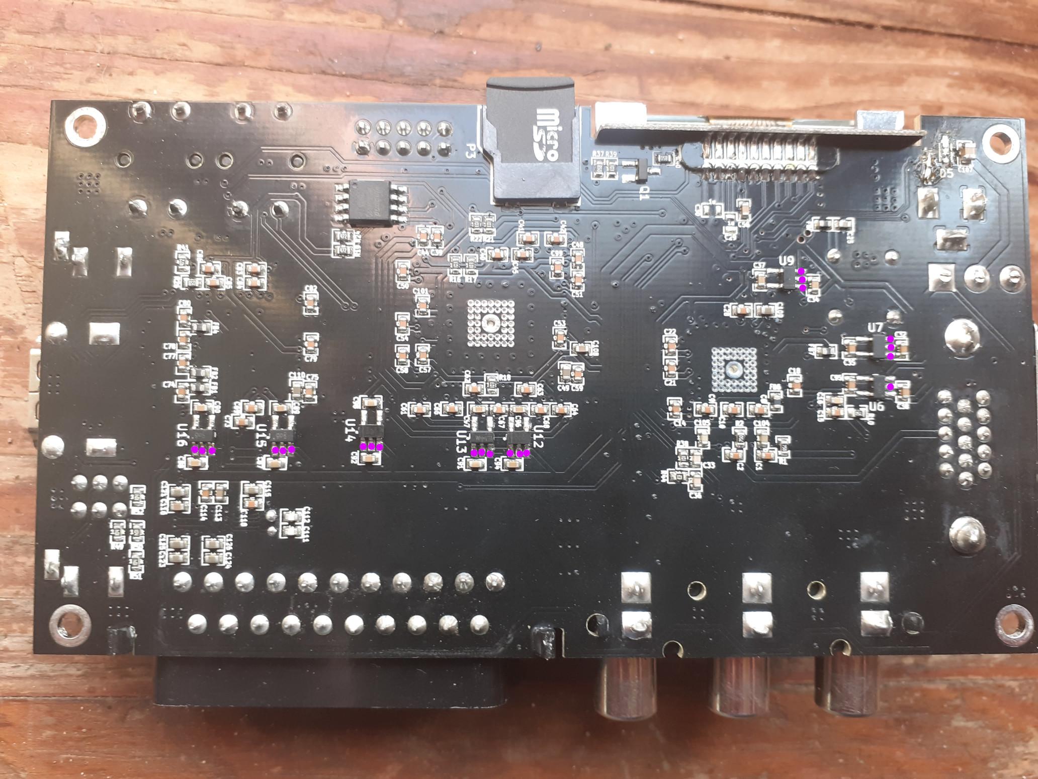
February 29, 2024 at 12:47 PM #60326So here are snapshots of my PCB with all regulators pins connected to ground marked (I checked all 5 pins for each of them). U4 does not look like a regulator but I checked it anyway…
Interesting thing is that only U6 seems to be OK :
-
This reply was modified 1 year, 7 months ago by
February 29, 2024 at 5:12 PM #60328So I decided to try my luck and unsoldered U5 (I was very carefull not to burn the LCD flat cable during that operation).
It went well and all other regulators do now show correct ground connection. I checked the extracted U5 and it indeed still has a short between pins 1 and 2 (same as shown in the pictures above). That explains I guess to super hot temperature it had ?
I’ll order a new U5 and also fuse and diode and see if it brings my dear OSSC back to life, just crossing my finger nothing else is damaged on the PCB 🙂
Just a noob question about ordering : I went on Mouser (as the OSSC BOM has direct links to them), but the shipping fees are veeeeeeery expensive (around 20€) compared to the few things I’d like to order. Would anybody have recommendation for another reliable supplier for Europe ?
February 29, 2024 at 5:12 PM #60329So I decided to try my luck and unsoldered U5 (I was very carefull not to burn the LCD flat cable during that operation).
It went well and all other regulators do now show correct ground connection. I checked the extracted U5 and it indeed still has a short between pins 1 and 2 (same as shown in the pictures above). That explains I guess to super hot temperature it had ?
I’ll order a new U5 and also fuse and diode and see if it brings my dear OSSC back to life, just crossing my finger nothing else is damaged on the PCB 🙂
Just a noob question about ordering : I went on Mouser (as the OSSC BOM has direct links to them), but the shipping fees are veeeeeeery expensive (around 20€) compared to the few things I’d like to order. Would anybody have recommendation for another reliable supplier for Europe ?
February 29, 2024 at 5:14 PM #60330Interesting -> your OSSC layout differs a bit from the official 1.6 layout… which can be found on marqs github:
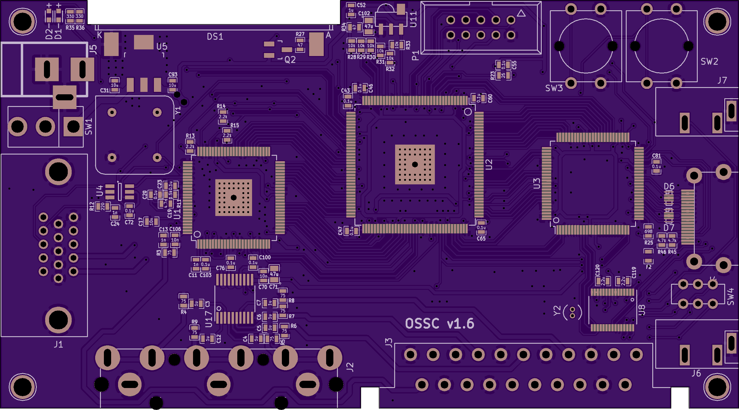
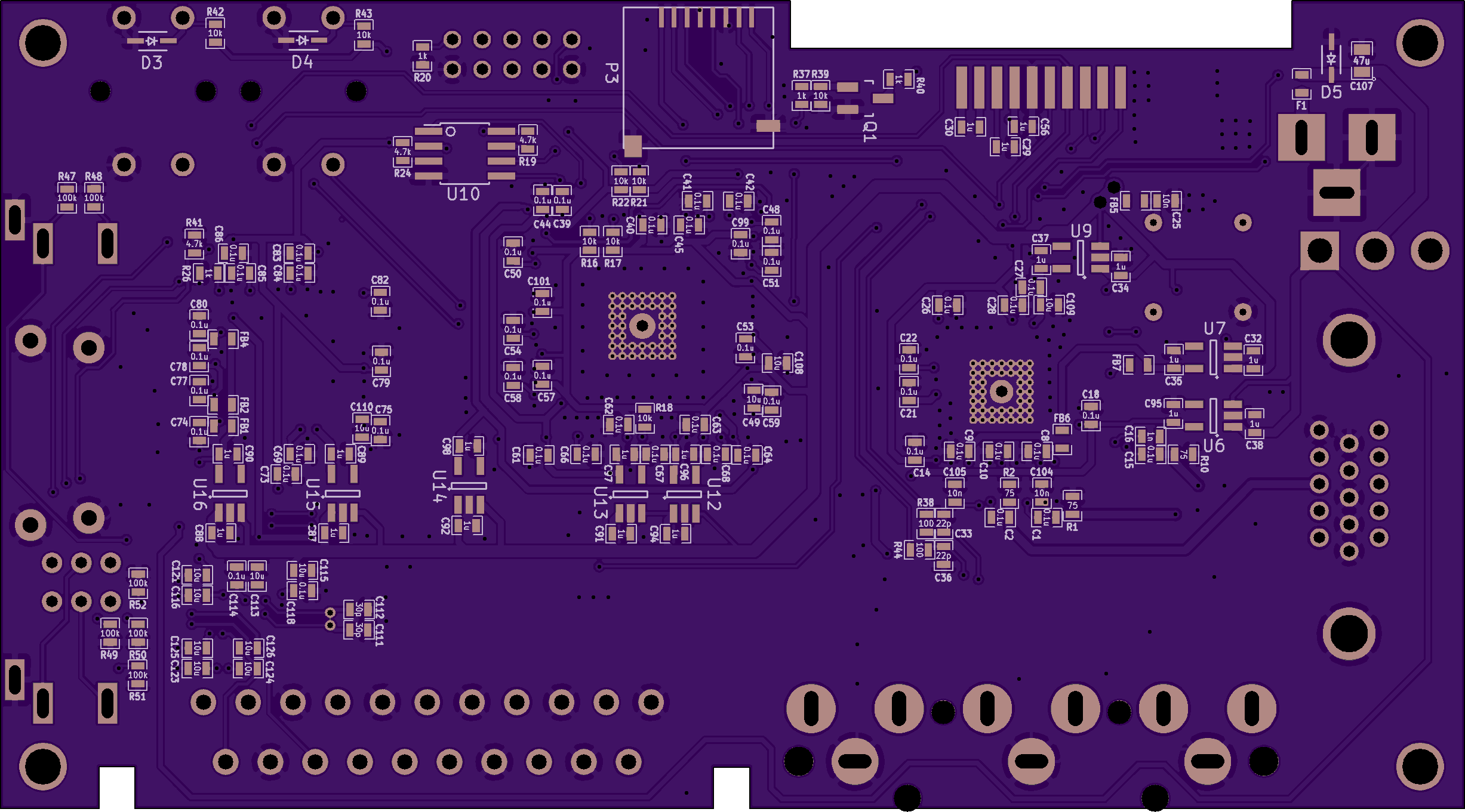
That could be problematic for finding a replacement part. Because i don’t know for sure, if for U5 the part from the official BOM was used. It is probably a different voltage regulator with a different pinout. I assume this, because:
- Your U5 is upside down, but the filter capacitors for the input and output voltages (= C31 and C93) haven’t switched places -> there must be a reason for it.
- Your U5 probably isn’t a AP7361C, since if it were, its 5V input would be connected to ground. But: that’s not the case for you, because it’s clearly visible in your pictures that the 5V input is connected to the outer of the three pins on U6, which are NOT connected to ground.
Switched input/output-pins for your U5 means: not the 5V input is shorted to ground, but its 3.3V output. Which would make sense: the input pins of your U7, U9, U12, U13, U14, U15 were all shorted to ground on your OSSC, which are all connected to the 3.3V output line of U5.
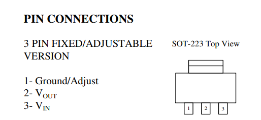
In conclusion: your OSSC uses a voltage regulator for U5, where (compared to an AP7361C) the input and output pins are switched. Which means: you can’t replace your U5 with an AP7361C, since it has the wrong pinout for your unofficial/modified OSSC! So: DON’T BUY AN AP7361C AND PUT IT IN! You would fry it!
Now for the more problematic part: what’s written on your U5? Since it is not a AP7361C, the markings may help to find a suitable replacement…
Would anybody have recommendation for another reliable supplier for Europe ?
For Europe i would recommend lcsc.com, tme.eu or rs-online.com. All provide reasonable shipping costs and have European warehouses or ship from/over European countries. While lcsc.com has the biggest selection of components, it’s the slowest for shipment, since it’s based in China.
-
This reply was modified 1 year, 7 months ago by
February 29, 2024 at 5:37 PM #60333Thanks a lot Morpheus_79, I did not realize my PCB was different and was about to order the wrong replacement regulator !
I check the label on my extracted U5 and it’s “AMS 117 3-3 LD818“. From what I’ve seen here: , it indeed has pin 1 for Ground, pin 2 for Vout and pin 3 for Vin.
We kind of double-posted here, but as I said in my previous message, pins 1 and 2 of my U5 are still shorten even when extracted. So I’m assuming the problem is restricted to U5 only ?
I do not remember where I ordered my OSSC but I can retrieve that information if anybody is interested. Maybe they changed the U5 for costs reasons or because it would no longer be produced in a near future ?
-
This reply was modified 1 year, 7 months ago by
February 29, 2024 at 6:03 PM #60336So I’m assuming the problem is restricted to U5 only ?
If the shorts on U7, U9, U12, U13, U14 are U15 all gone (on the rows with the three pins: only the middle pin should be connected to ground), then only U5 was faulty.
Maybe they changed the U5 for costs reasons or because it would no longer be produced in a near future ?
It’s still available and will be produced in the near future. But it’s harder to get from local suppliers in some countries. There are some very similar voltage regulator from smaller Chinese manufacturers (AIC1221-33GY3TR… MIC37100-3.3WS) with the same package size and pinout as the AP7361C:
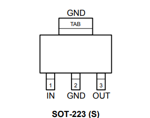
I can understand using the AMS1117… since it is VERY common and readily available in most countries… BUT (as you’ve said) it has a pretty different pinout though:
So in the end it probably was cheaper to change the pcb layout and use an AMS1117, since their cheapest versions go for around 3 Cents per part, while the AP7361C and its suitable replacements cost around 6-8 times that price.
February 29, 2024 at 6:25 PM #60337Perfect !
I’ll check the suppliers you recommended, order everything (with a few extra spare AMS117), and let you know of my results.
Thanks a lot again Morpheus_79 for all your valuable and quick answers 🙂
February 29, 2024 at 6:41 PM #60338I’ll check the suppliers you recommended, order everything (with a few extra spare AMS117), and let you know of my results.
Pay attention to buy a version of the AMS1117 which outputs fixed 3.3V (since there are also versions available for other fixed voltage outputs, like 1.8V… and a version with an adjustable output too -> which all won’t work).
Thanks a lot again Morpheus_79 for all your valuable and quick answers 🙂
You’re welcome.
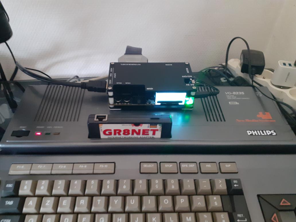
March 9, 2024 at 2:41 PM #60581Yes, my dear OSSC is back from the dead 🙂
I order the components at LCSC for $12.05 inluding shipping on March 1st, and received everything today.
SMD soldering is still a painful experience for me, those things are sooooo tiny !! I had to unplug and secure the LCD flat cable to avoid burning it with the soldering iron, but it all worked well finally.And now, I’ll just enjoy a good video-perfect gaming afternoon 🙂
PS : If anybody happens to have the same issue (shorted regulator) with the same “special” PCB as I have, I can snail-mail the part (as I’ve order 5x units). I also have 4x remaining D5 and F1.
March 9, 2024 at 7:56 PM #60591Congratulations 🙂👍
-
This reply was modified 1 year, 7 months ago by
-
AuthorPosts
- You must be logged in to reply to this topic.