AlexS
@alexs
Forum Replies Created
-
AuthorPosts
-
Thank you, hopefully this is our last question 🙂
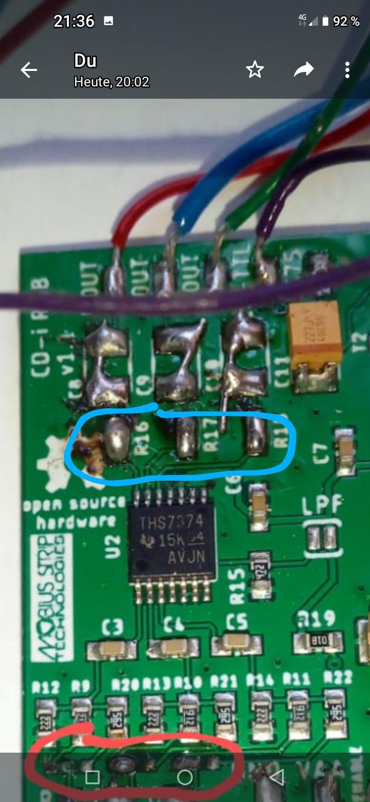
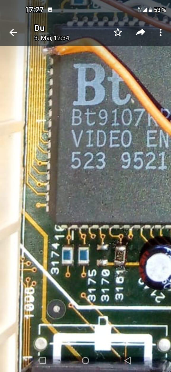
We removed these three resistors, might this be part of the problem?
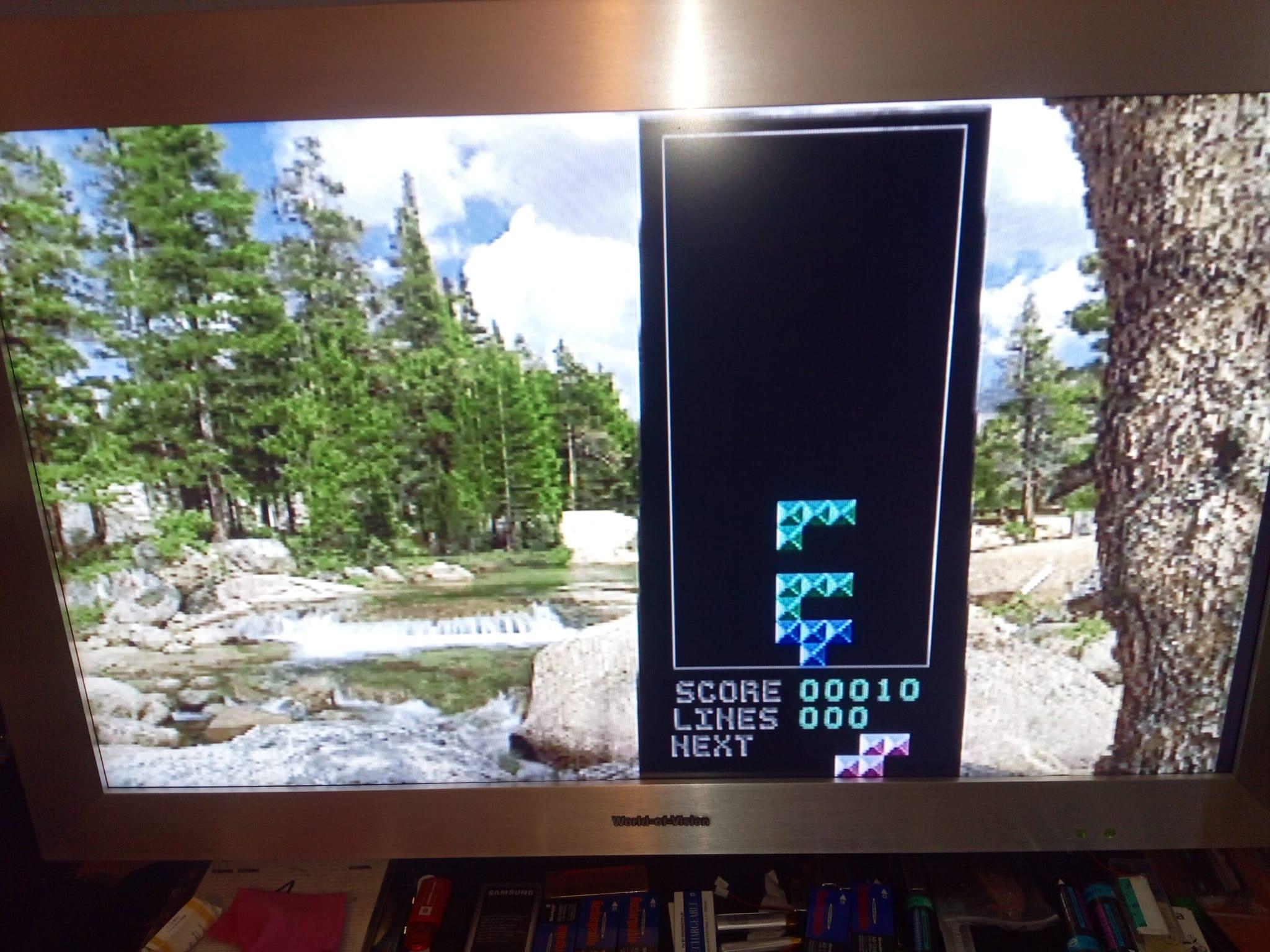
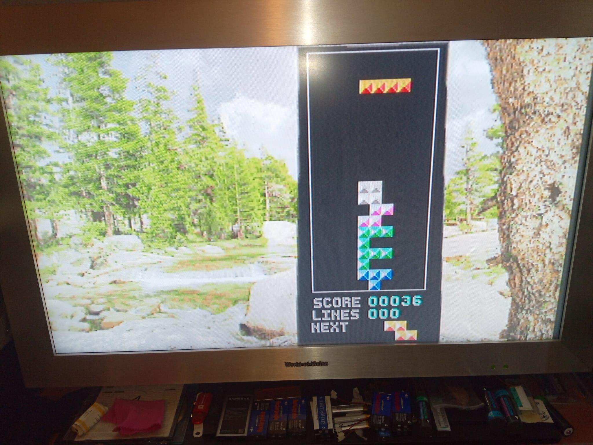
Thank you for your help, it’s working! Mostly. All jumpers are left now, but is it normal that conposite is still working? Also, the image is too bright, see the pics below. Any final clues to solve this would be very welcome. Thank you!
-
This reply was modified 1 year, 3 months ago by
AlexS.
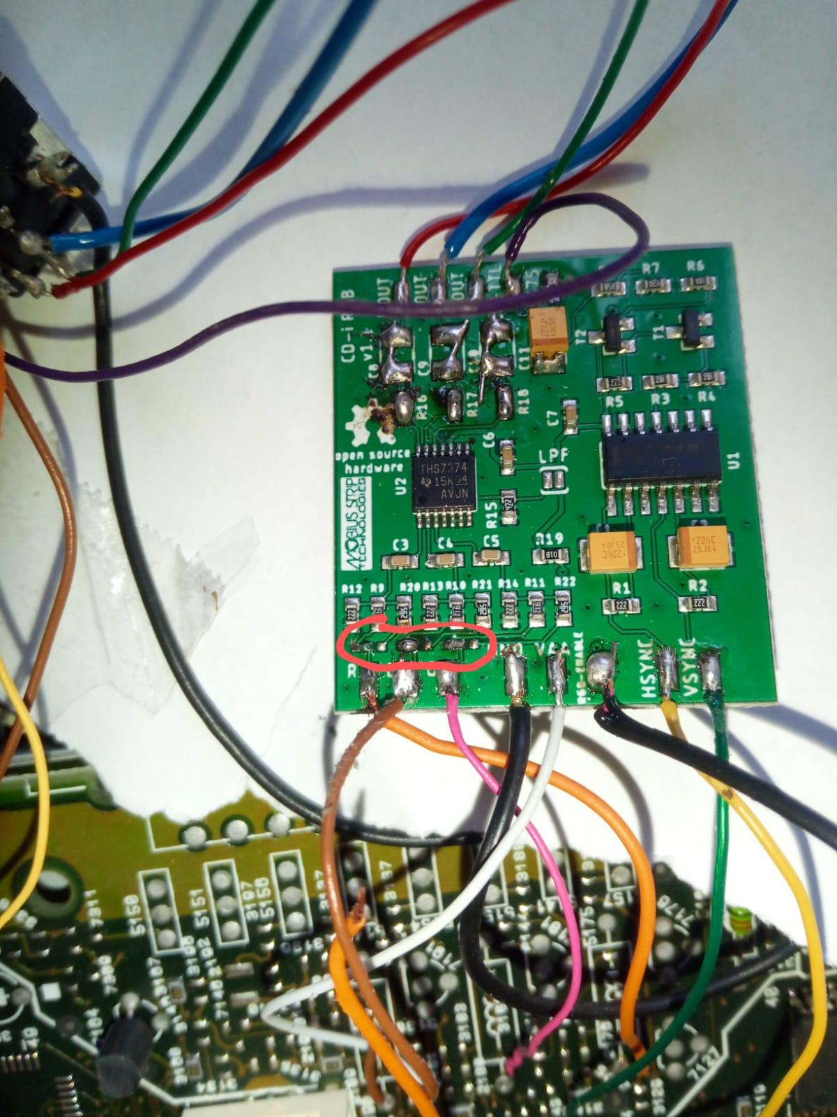
About the last pic I posted: here the resistor is set on 3161 which should activate RGB. 3170 is composite video, this resistor is on the back side on mass flow/minus but it could also be done on the front side on Plus. Any idea which one is the correct one? Thank you!
Back again, still not done. Our assumption is that we have to remove the resistor from pin 13, this might activate RGB. Anyone can confirm this?
Also about your second hint:”They also don’t need to solder the RGB enable pad because they moved the resistor on the mainboard” does this mean we don’t have to do part 4 of your instructions, because we did part 5, removing the 3171 resistor? Sorry that we need to ask so often, but this seems to be trickier than expected. Thank you for your help
<p style=”text-align: left;”>Of course I mean this part, please forget the upper posting:”470 (Tested Working. Requires Solder Jumper to Left.)”</p>
Of course I mean this part, please forget the upper posting:”470 (Tested Working. Requires Solder Jumper to Left.)”
I’m sorry I have to ask again, but just to be sure: are you referring to this part on your github-page:”Built-in RGB Enable pad. No more soldering in a pull-up resistor.”?
Thank you very much for your help, I hope this will do the trick
-
This reply was modified 1 year, 3 months ago by
-
AuthorPosts