oddz
@oddz
Forum Replies Created
-
AuthorPosts
-
Ok so after hours of research, I finally found the way to do it looking at random pictures posted on twitter. So if someone is looking for the same thing, here is the way to connect your cables on a Megadrive PAL VA4 :
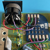


Don’t forget to cut the pin 50 on the VDP ! No need to cut any leg on the CXA1145.
I read that you can add 4.7uF cap between RGB VDD / RGB GND, and between Digital VDD / GND.The result is very disappointing in my opinion, the jailbars are still very visible, the improvement is subtle in my case.
There is no tutorial for VA4 all over the internet 🙁 it seems that a lot of people have issues with this version.
This is what I have done, I had connected the 5v and GND pad like in the guide but I saw many people connecting these like that, so I thought I was going to give it a try. It still doesn’t work. If someone could tell me what I’m doing wrong, it would be great, thanks.


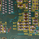
Finally, I followed the circled via to the top side of the motherboard, I cut just after the via, then scratched the green to reveal copper and soldered there. I finished the mod, tested it, but I have no synch. Checked everything and it seems fine, I don’t understand.
I don’t know about the board, I bought it second hand on Ebay.
I don’t think my measurements are wrong, I checked again.
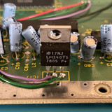
I have ground on the middle pin (on the 3 pins side) on all regulators except on U5. U6 and U16 have one pin shorted to ground on the 2 pins side, and U5 has 2 pins shorted to ground on the 3 pins side. U3 seems ok.Ok, so after tests, U6 and U16 have one pin shorted to ground on the 2 pins side, and U5 has 2 pins shorted to ground on the 3 pins side, the middle one is not shorted to ground which is weird, no ?
Thanks for you reply,
I plugged in a 12V PSU. The LCD works just fine and shows no error, it reacts well to the remote controller too, channels, etc…
Not sure how to check properly if voltage regulators are shorted, they have 5 pins. I place the red of my multimeter on one pin and the black on ground, if I have continuity the component is dead, right ? -
AuthorPosts