DIY Guides, Howto & Guides, News, Site News
Fixing the GamesCare Switch Audio Issues
Update May 2025 – Revised the instructions for improved product performance and long term reliability.
Update March 2025 – Fixed error where it said “pin 6” but the photo showed pin 7. Pin 7 is correct.
A number of customers who purchased the GamesCare Smart SCART switch or the GamesCare Component Video Switch noticed that when using the switch with high quality audio equipment, certain sounds were distorted or corrupted. We have investigated this issue extensively with the help of both GamesCare and BetaGamma Computing and created a fix for this issue, which affects both products (and the GamesCare SCART switch expansion).
Note that this is NOT a product safety issue. There is no risk to you or your equipment. If you are satisfied with the performance of the switch, you do not need to do anything.
If you purchased your GamesCare product from us, you are entitled to get this upgrade done for free. Please use the contact form here, and send us your order number, so we can advise you on the best way to return the switch to us to have the upgrade installed. If you purchased your GamesCare switch from elsewhere, BetaGamma can upgrade your switch for a small fee, or you can install the fix yourself or have a local modder do it.
Smart SCART Switch Firmware 2.1
All Smart SCART switches now shipping and any that we repair will also have the new firmware version 2.1 installed, which fixes some other minor issues with the device and has the following new features:-
- User selectable pin 16 signal voltage – Allows for full compatibility with older CRT TVs that require appropriate signal voltage on SCART pin 16
- Faster start up time
- Automatic over-the-air updates for any future firmware
- LCD Menu allowing configuration of advanced features without the need for a Wi-FI connection
DIY upgrade instructions
BetaGamma computing have kindly provided a service bulletin with instructions on how to install this upgrade. details of this can be seen below, or you can download it directly in PDF format here.
VGP Service Bulletin – GamesCare Switch units May 2025
This service bulletin describes modification details for the GamesCare suite of switches (Smart SCART, Automatic Component Switch and SCART Expansion).
This revision 2 of the bulletin has been updated to reflect further improvements to the products, both for performance and long term reliability.
Note that this is NOT a product safety issue. This upgrade is optional but can be implemented if the user finds issues with the audio output of any of the three products.
To complete the upgrade, there are two modifications that need to be implemented.
The first modification involves the replacement of two onboard analogue switch chips and changes to their bias arrangement. This increases the headroom and provides true AC signal output. One chip handles left audio, the other chip handles right audio.
Although this modification applies to all three products, the Automatic Component Switch already has the newer analogue switch chips fitted from the factory so only some rework is required, not a complete chip replacement.
The second modification applies ONLY to the Smart SCART switch.
The Smart SCART Switch buffers the audio outputs through a unity gain operational amplifier. Some production units were manufactured with an LM358 OpAmp but a TL972 is preferred as this is a higher performing device and will drastically improve the audio performance of the device.
These modifications are all SMD rework level and require a very high level of competence to be correctly carried out. Suitable rework station, fluxes, and solders are required. The modifications should NOT be attempted unless you are confident and skilled to carry out the rework.
VGP offer an upgrade service for ALL of these products regardless of source of purchase, please get in touch if you need this rework carried out.
In all cases the units will need to be stripped down. All plexiglass plates and stand-offs need to be removed. Please pay careful attention when disassembling and perform the same steps in reverse to reassemble the units once work is complete.
The following is a list of components as referenced by this bulletin and recommended links for suitable sources are provided.
Parts Needed for all 3 Products
1. 5V Buck Convertor
https://www.aliexpress.com/item/32955462579.html
or a similar device with 200mA capacity.
QTY 1 required per product.
Parts needed only for the Smart SCART Switch and Expansion Unit
2. higher rated analogue switch IC (Texas Instruments CD4051BM96).
https://www.mouser.ie/ProductDetail/Texas-Instruments/CD4051BM96?qs=0le1rQK8zxqMHlJa1GNAzQ%3D%3D
QTY 2 required per above product.
Part needed only for the Smart SCART Switch
3. Higher performance op-amp (Texas Instruments TL972IDR).
https://www.mouser.ie/ProductDetail/Texas-Instruments/TL972IDR?qs=oFh0aswXlb%252Bs7%252BxhuL08lw%3D%3D
QTY 1 required per switch.
Smart SCART Switch
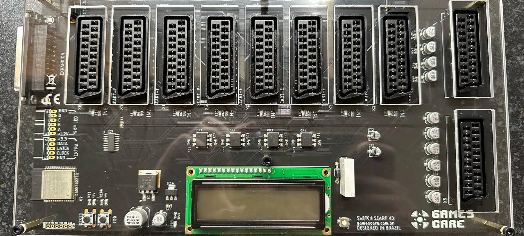
All rework is carried out on the rear or solder side of the board. Click or tap on any image on the page for a bigger view.
1. IC5 and IC6 Replacement & Buck Convertor Installation
Examine the above image and locate IC’s 5 and 6
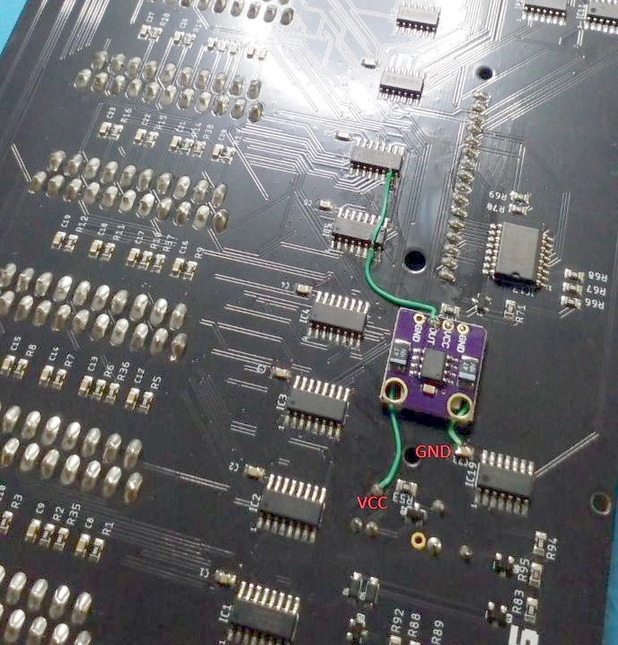
Using SMD rework tools, remove both IC5 and IC6, these will be replaced with uprated versions of the IC.
Before soldering the new IC5 and IC6 components, lift pin 7 of both IC’s, ensuring they are clear of the PCB pads.
When soldering the chips into position, do NOT solder pin 7 on both IC’s. Ensure these 2 pins, one on each IC, are both kept clear of the PCB.
Fit the buck convertor in place using a suitable insulated fixing method and wire up as shown in the photo above using Kynar 28 awg hookup wire.
Ensure there are no shorts between VCC and GND before connecting power.
2. Op-Amp Replacement
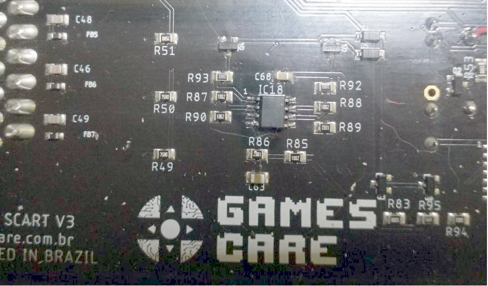
Locate and remove IC18, fit the new OpAmp in place.
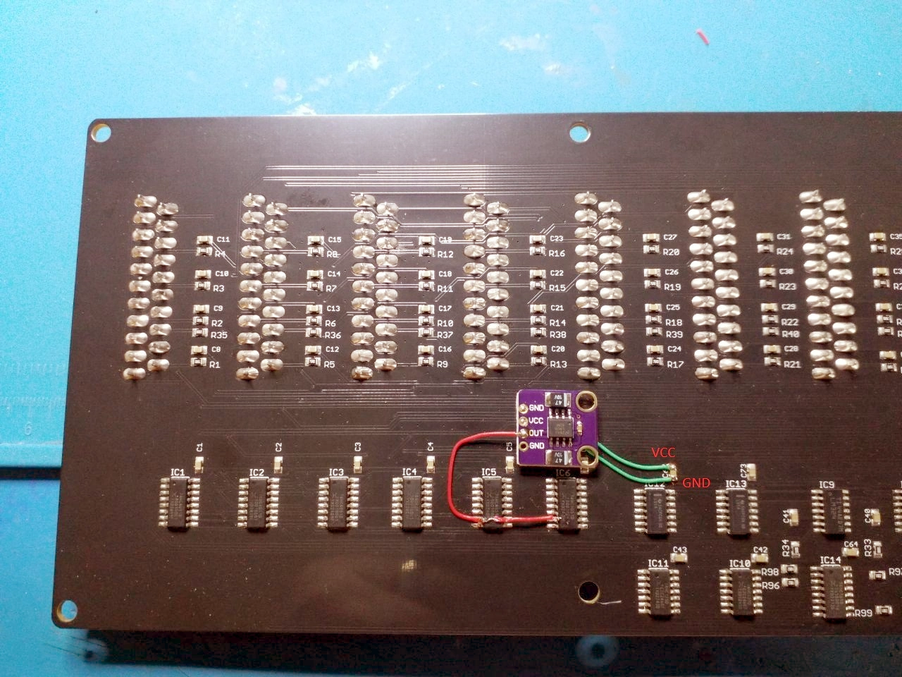
SCART Switch Expansion
The following image depicts the different component locations compared to the main switch unit.
The circuitry change rework is identical to the main switch unit, apart from there being no op-amp replacement required.
Component Switch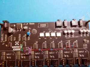
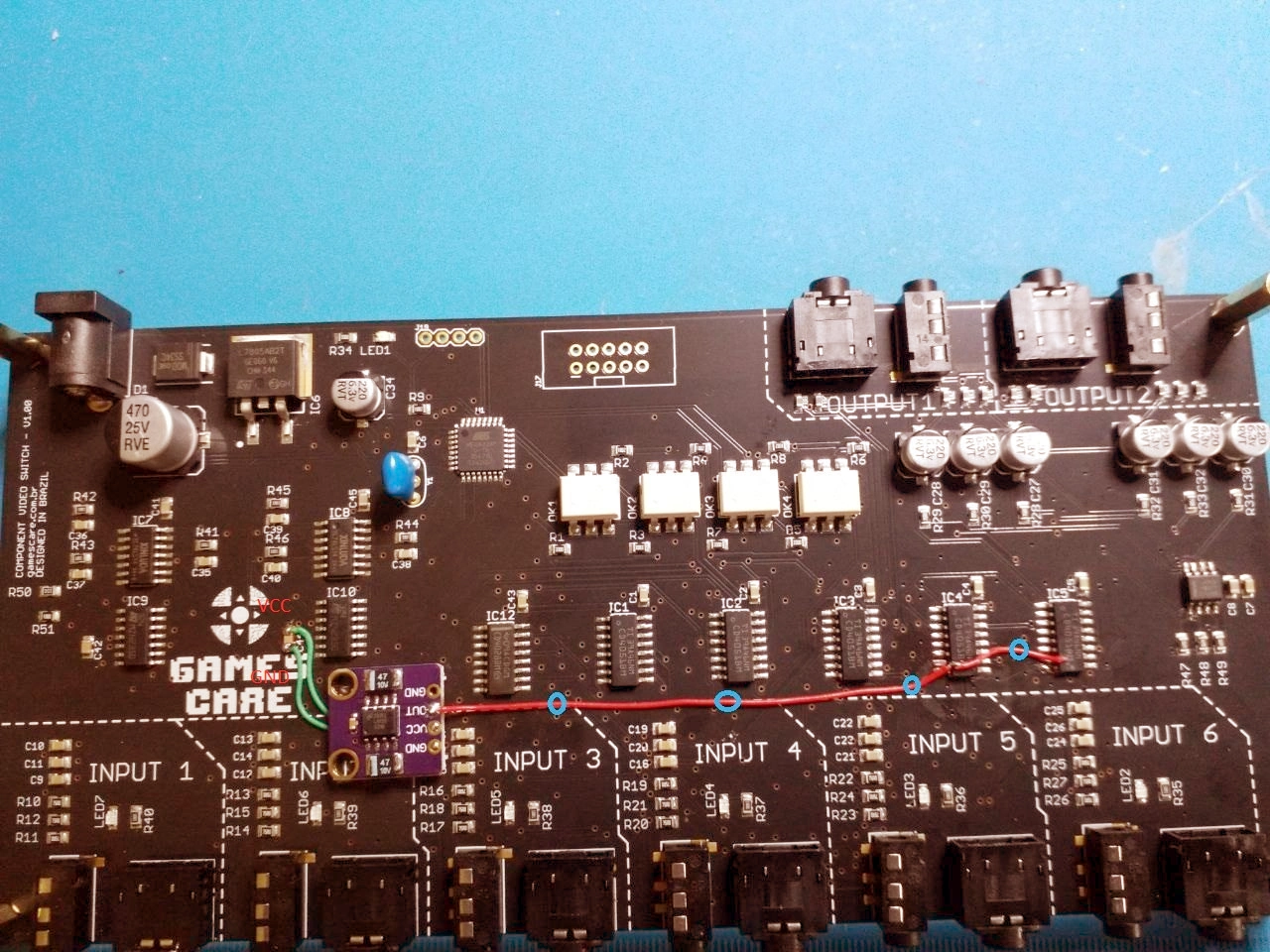
The procedure is largely the same as the SCART switch apart from:-
- The modification is carried out on the top side of the board.
- There is no op-amp to be replaced.
- IC 4 and IC 5 are only to be reworked and not replaced.
Using suitable rework tools, pin 7 of IC4 and IC5 must be carefully lifted ensuring that they are clear of the PCB pads.
Once the wiring has been completed as shown above, it is highly recommended to use some Bostik Fix and Flash, or similar glue, to secure the wire to the points circled in blue in the above photo.
Bas Gialopsos – BetaGamma Computing – 19th May 2025
The images are a little blurry. The instructions say to lift pin 6, but in the images it appears pin 7 is lifted and connected to the wire. Is it pin 6 or pin 7 that should be lifted? And to which pin should the wire be soldered to?
Thanks for that! You are correct, it’s pin 7, I’ve updated the documents.
I have a GamesCare Component Video Switch I ordered from a different site. I’d like to use your upgrade service. How can I start that process? Thank you!
See the page here – https://videogameperfection.com/products/gamescare-switch-fix/