[REQUEST] A updated part list for OSSC 1.6?
NewHome › Forums › OSSC, OSSC Pro and DExx-vd isl › OSSC – DIY & Repair Support › [REQUEST] A updated part list for OSSC 1.6?
- This topic has 49 replies, 11 voices, and was last updated October 14, 2018 at 12:47 AM by
Morpheus_79.
-
AuthorPosts
-
August 22, 2017 at 12:32 PM #14614
Ok guys 🙂 heres the update.

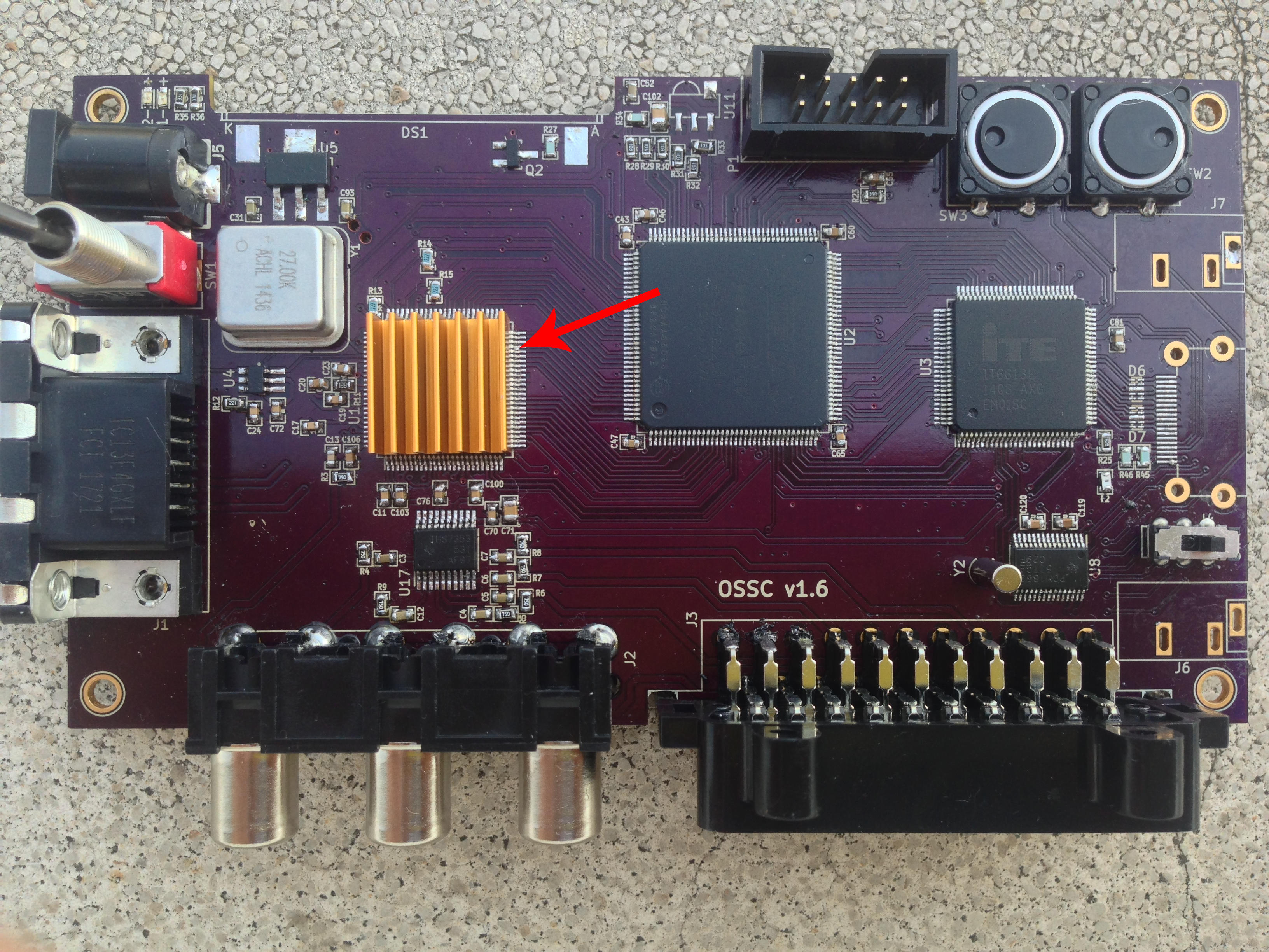
Well, I must say everything is going its way… You can check the current state of the product in the photo.
I ran into some Chip pins bends that was incredible hard to solve due the minuscule size of them, but thankfully I had a 0.5mm sodering point and a x10 glass that make my life somewhat easier…
Now that the top side of the board is finished, I realized that I made quite a lot of mistakes soldering the bottom Res. and Caps. with a 1.0mm point, and since I cannot trust my work down there, The only solution is to redo all the work underside, besides the biggest chips and voltage regulators, that adds up to another 50+ components to go, sight…
I will place the LCD the very last thing, that’s why its currently missing from the photo. :p
Now The issues:
I have no f clue how to solder the D6, D7, #59 ESD Suppressors / TVS Diodes, really, they have no pins and they beat me, the pads are also almost invisible small and, even with my soldering tech of pre-solder the pads, I’m afraid of doing something and ruin the components, since, they are so small I left the HDMI out for now since I will not be able to access them so easily if I solder it in place.I’m missing the U7, #8 voltage regulator since mouser again is out of stock, this is the biggest component that I need right now… ¿any alternative?
And that’s pretty much it, the same parts as before are still out of stock in any page that I checked (ir receiver…), so now I’m just waiting for some input from you guys, on that missing voltage regulator, and I will order the last batch of components before switching the thing on and praying for the best.
If successfull I will upload a new tutorial with photos and everything, so you don’t have to make the same mistakes I did. lol.
Oh yes, almost forgot: The push buttons SW2 & SW3, and the Y2 frequency barrel crystal can be placed in any direction right? Their orientation wasn’t defined so either way is fine, or so I though. Also the D6 and D7 do they have an orientation, but I’m somewhat lost about the placement, I see a dot on the chip itself but I’m not sure how to position it on the board with the placement marks. ¿Any info on this?
cheers. 🙂
August 22, 2017 at 1:25 PM #14620Hi OOQQ,
I’ve built 6 OSSCs successfully so far, so maybe I can help.
For the RCLAMP parts, I managed to solder these with just a standard iron and medium chisel tip, believe it or not. It’s not easy but it’s possible.
I’d recommend a strong magnifying glass or microscope, or if you have none of these (like me) use a good camera with zoom/macro feature so you can check your work.
Tin the pads on the PCB thoroughly – make sure you get all of them as they’re tiny, and put lots of flux on both them and the components.
Hold the part in place with tweezers, get a large bead of solder on the end of your iron, and run it up and down the side of the part until it flows underneath. The part will want to almost “snap” into place due to surface tension.The centre pad runs through both sides of the part, so once you have that pad soldered, the rest becomes easier.
When you think you have soldered one side, wipe your iron, flux the other side of the part, get a new bead of solder onto the iron and again, run it along the edge. Take care not to knock the part off the pads – use tweezers to help stabilise it.
Check your work frequently, and eventually you should have the following: (click the images to get fullsize)


Also – note the orientation. When looking towards the back of the HDMI port, the text on the RCLAMP parts should be readable and not upside down.
Once you think you are done, check continuity between the pins of the IT6613 and the HDMI port – just follow the traces that go through the RCLAMP parts. If you get continuity, you are golden. Also check that adjacent pints are not shorted.
If you have a hot air station, it gets much easier, as you can tin and flux the pads, place the part, and just heat it. The surface tension makes it simply snap into place.
Button orientation – yes, they can be placed any way. I like to put the dots towards the left as you look at the front of thew OSSC, but it’s just personal preference. The 2-legged crystal also can be placed any way.
Do you still need IR receivers? I have a small stock of these, about 4 I think. Where are you located?
Also, did you order from OSH Park? If so – nice – it looks like the plated slot fixes I sent to marqs have worked for you too, so that double-verifies them 🙂
Hope this helps – good luck!
August 22, 2017 at 1:44 PM #14626Yes I do need one IR receiver. Im from spain – europe, but I don’t mind the shipping costs, the part is out of stock anywhere so, if you sell, I buy :p
Thanks for all the tips, yes I do have a multimeter and standard tools, no microscope or fancy stuff, so no hot air tech lol, but I do believe I eventually will make it. :p Also thanks for the continuity tip, you can believe I checked continuity on everything, it’s actually the only way to be sure.
Apparently, I can use this
as an alternative U7 voltage regulator, so I have everything now :), except the bloody IR receiver lol. I hope it’s not mandatory to operate the OSSC
August 22, 2017 at 2:15 PM #14631Spain is no problem, I’m in the UK so it won’t cost much.
Also, if you need a remote control, I found a very cheap and good quality remote here in the UK that only costs £1.00 GBP:
It has a huge list of codes to use with different TVs, and I found one that allows nearly all of the buttons to be mapped to OSSC functions.
If you like, I’ll go buy one and send it to you with the sensor.
I will add this information to the wiki shortly in case it helps anyone else. 🙂
The IR receiver is essential to navigate menus and change options – without the remote, you won’t be able to do anything apart from switch inputs and scanline modes using the on-board buttons.
August 22, 2017 at 2:18 PM #14633Sadly I purchased the oficially licensed CHUNGHOP™ from the store, so thank you but I do not need another remote :/
I will give you my adresss via PM 🙂
edit: fk theres no pm option in this forum lol xD
August 22, 2017 at 2:23 PM #14637Hi d0pefish, if you still have them, I’d like to buy a sensor from you.
I’m interested by the remote as well because I forgot to order one with the kit. I’m from France so shipping shouldn’t be too expensive.August 22, 2017 at 3:03 PM #14640If you still have an IR receiver I’m also interested, I’ll contact you via PM.
August 22, 2017 at 3:12 PM #14643No problem guys, you can all buy my spares.
I’d like to keep one as a spare for myself though, so I’ll have no more available after you guys.
OOQQ/Nehalem501/philenotfound – email me at daleyo at gmail dot com with your shipping addresses and I’ll reply with the cost.
The IR sensors cost me £1.50 GBP, so that’s all I’ll ask + shipping.@OOQQ: No problem, the Chunghop is a nice remote. This one doesn’t have the learning ability, but is a good cheap alternative if you don’t care about the learning.
@Nehalem501: I’ll pick up a remote today for you.August 23, 2017 at 4:56 PM #14705Just a quick update – IR receivers (+ remote for @nehalem501) dispatched to all three of you today via airmail.
Please allow up to 5 days for delivery – hope they all reach you safely.Thanks 🙂
August 24, 2017 at 2:07 PM #14732Thank you! 🙂
August 25, 2017 at 3:54 PM #14760Ok guys:
http://imgur.com/a/56XNL
but no image or sound :/.other ports equally black. Green led lights, button 0 correcly cycles ossc between inputs. OSSC screen correctly detects between 50/60hz saturn switch on the fly.
edit: Im gonna test the other ports.
edit: main chips & voltage regulators runs extremely hot after a couple of minutes on idle.
August 25, 2017 at 11:34 PM #14770RCLAMP ESD diode arrays are not absolutely necessary, but if they are omitted then HDMI cable hotplugging should be avoided.
If the large ICs or regulators run hot with no input, it indicates there is a short somewhere on the board.
August 26, 2017 at 5:20 AM #14774I don’t know, if you already solved it after taking the picture – but this pin on the TVP7002 looks bent and is awfully close to the pin next to it:

If you do some resoldering (especially on the fine pitch pins of the ICs the HDMI connector): use some good flux. It makes soldering a lot easier, since with flux the solder wont stick on the soldering tip like glue but just evenly flows on the solder pads.
August 28, 2017 at 10:26 AM #14793You are both right, I have a disgusting amount of continuity in every connector pin 1 with 2, 3, 4, 5, 6… etc (SCART, Component…), so after a little more reading, overheating & continuty issues are idicative of shorts, and after careful inspection, the culprits are absolutely the ICs.
Now the bad news. My glass isn’t strong enough to dectect WHERE the bridge is, and I messed up the soldering, now theres solder in top and botton of the IC pins, so my options are.
1. Buy a better magnifyin glass and try to fix it.
2. Buy Quick Fix and desolder and somewhat clean the pins and remount
3. Desolder the three and buy anew.I will try the three methods in order, from cheapest to expensive. Now that I did some cleaning, the problem is worse since I got no more text on display lol.
edit: I got the IR receiver by mail, thank you @d0pefish 🙂
August 28, 2017 at 2:10 PM #14799You’re welcome! 🙂
I also got a mail to confirm @philenotfound received his too.Good luck with the troubleshooting – you should be able to fix the bridge with some flux and some patience.
A couple of times, I found that too much flux and too many attempts at cleaning results in semi-conductive residue becoming trapped under the chips, causing subtle, hidden shorts that show up as unstable sync or the FPGA’s CPU crashing (garbled display).
To fix these, desoldering, cleaning, and re-soldering the TVP and/or Cyclone was the solution, as attempts at cleaning under the chips with IPA failed. So far no chips have died doing this – although I am experienced with SMD/hot air rework tools. Hopefully it won’t come to this for you.
-
AuthorPosts

- You must be logged in to reply to this topic.