manuelink64
@manuelink64
Forum Replies Created
-
AuthorPosts
-
Hi guys,
i’m new on the retrogamnig, I’ve some original console (from my childwood), like NES, SNES, ecc. I’ve found a McBazel OSSC board on Amazon (1.6 board), but when I use it on my consoles I did’t see the video on the monitor.
All the console comes out with a RCA cable, so i think the video signal is composit and not RGB. Question: if I mod the board and put in a new fw I resolve my problem or I still need a converter like RetroTINK-2X?
thanks guys and sorry for a “newby question” 🙂
OSSC works only with RGB or Component signals, but If you have an OSSC, you can buy (cheap) RGB Scart cables for the mayority of your consoles on AliExpress, if you want to use Composite/S-video, you can buy the add-on for OSSC called Koryuu Transcoder.
-
This reply was modified 4 months, 2 weeks ago by
manuelink64.
Thanks @morpheus_79, I really liked your response ;). What cable you used (looks like a enameled one)? I used wire wrapping (AWG 30), but the heat burn the jacket.
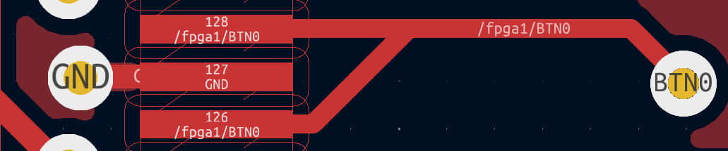
For the other crazy guys trying this mod, the PCB layout speaks by itself:
PCB V1.6, Pin 126 on U2, connected to GND under the chip itself
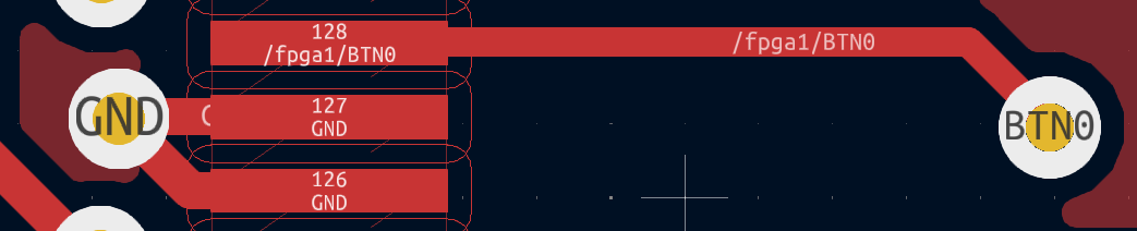
PCB V1.8, Pin 126 on U2, connected to pin 128, so pin 126 is necessary to be lifted and connected to pin 128 on V1.6 to become a V1.8 PCB
The other part of the mod:
PCB 1.6, The pin 22 on U1 is connected to pin 98 on U2. pin 25 in unconnected
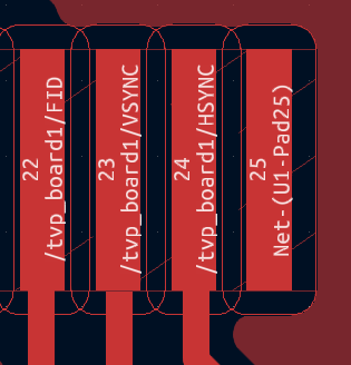
PCB 1.8, The pin 25 on U1 is connected to pin 98 on U2, pin 22 is unconnected.
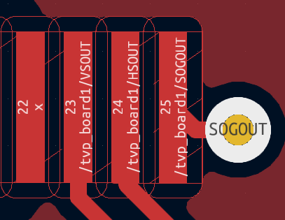
So for the convertion, on PCB 1.6 you need to lift the pin 22 on u1 (or cut the trace) and reconnect pin 25 on the path of pin 22.
-
This reply was modified 1 year ago by
-
This reply was modified 1 year ago by
Hi marqs, thanks for the detailed response. But I want to try the “hard way” mod, so…
if I lift the pin 126 and solder that leg to the pin(pad) 128 I will be OK?
To @marqs @Xrider @morpheus_79
in the schematics of V1.6, are the pins 126 and 127 connected to ground on the PCB ?
the images of the amazing soldering job by @morpheus_79 doesn’t show the pin 126 lifted, and why he (re)connected the pin 127 to ground?
if I want to convert my v1.6 to V1.8, is neccesary lift the pin 126 and connect that lifted pin with the pin 128?
-
This reply was modified 1 year ago by
works great, amazing job my dude!
it’s posible to use your website offline (or local)?
-
This reply was modified 1 year ago by
Hi Paul, can you update your awesome OSSC Profile Web with the latest OSSC FW V1.10?
Until v1.09 works like a charm, but the latest FW version doesn’t work and the OSSC refuse to import the settings.
Cheers!!
what mod is the better one?
– The 1st one, removing SMD resistor R35 and adding a wire between TVP7002 pin 25 (last on the side) and FPGA-end pad of the removed resistor.
– the 2nd, solder a thin enameled wire between pin 25 of U1 and pin 46 of U2.
– the 3rd, rewire the connections between U1 and U2 on an OSSC 1.6 to match the connections on an OSSC 1.8.
I can perform all of them, but the 3rd looks more interesting, because the red led is still working.
-
This reply was modified 4 months, 2 weeks ago by
-
AuthorPosts