spacesaver
@spacesaver
Forum Replies Created
-
AuthorPosts
-
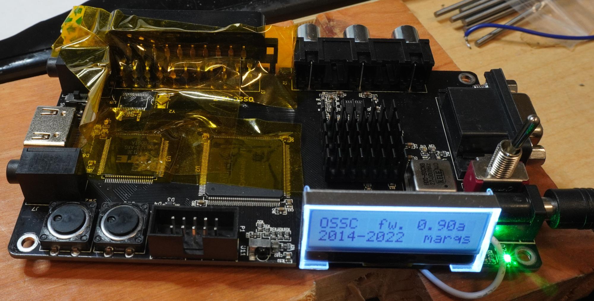
April 29, 2025 at 12:02 PM in reply to: v.1.7 not working even after JTAG flashing; how to debug? #65875
Hurray again. Audio input is back now. The replacement ADC and LDO regulator arrived from DigiKey today and I’ve installed them. I had a difficult time aligning the pins for soldering. I even ripped 1 of the traces when trying to realign, but miraculously, it was the IOVDD line, which can be shared with DVDD next to it.
April 23, 2025 at 7:03 AM in reply to: v.1.7 not working even after JTAG flashing; how to debug? #65807Hurray! it’s back after desoldering the audio ADC. I got no HDMI output at 1st because the U6 regulator was damaged and only outputting 1.7V. I fed U5 into U6 and got HDMI to work. I noticed the VGA signal was noisy around sharp edges, which is what you warned since analog power is supposed to be separate from noisy digital ones.
Very glad this unit was saved. Thank you very much Morpheus for the insights. Someone should check if the I2C code for the ADC will hang forever if the clock is pulled low indefinitely. I didn’t get to check before I desoldered.
 April 21, 2025 at 8:21 AM in reply to: v.1.7 not working even after JTAG flashing; how to debug? #65787
This guy also had a broken U6 regulator. https://videogameperfection.com/forums/topic/trying-to-repair-a-dead-ossc-u6-and-u1-were-replaced-boots-but-no-test-pattern/
Aha, I know 1 thing that’s broken for sure: the PCM1862 ADC (U8). I injected 3.3V externally through the U6 regulator output pin and it draws ~10A ! I touched all the chips that it powers and only U8 got hot. U1 is hard to tell because it’s so big and will take a long time to heat. That makes sense U8 got damaged, assuming that’s what the analog audio input connects to – I see pins named I2S in ossc_board.pdf, so that means audio.
This seems to be a case of permanent latchup. I’ve seen many microcontrollers ruined by latchup, presumably from applying signals before power, causing the gate voltage to exceed VDD.
Before I replace components, is it expected for the firmware to not print anything on the LCD? Does it mean it’s stuck forever reading/writing I2C and not getting a response?
April 21, 2025 at 2:32 AM in reply to: v.1.7 not working even after JTAG flashing; how to debug? #65782Hmm, on my OSSC 1.7, U5 is this regulator and the 3.3V output pin is the middle of the 3.
https://mm.digikey.com/Volume0/opasdata/d220001/medias/docus/5011/AMS1117.pdf
I don’t know how to tell if I have the reference design or a clone. I bought it in 10/2023 for $184 on eBay, so it seemed reputable.
Anyways, U5 is OK, as far as I can tell.
I checked VCC on the W25Q16JV flash chip and it is 3.3V. How can that be if you say U6 powers it?
Regardless, how about I connect the output of U5 to the output of U6 since you said they’re both 3.3V, and see if that fixes it?
 April 20, 2025 at 12:43 PM in reply to: v.1.7 not working even after JTAG flashing; how to debug? #65780
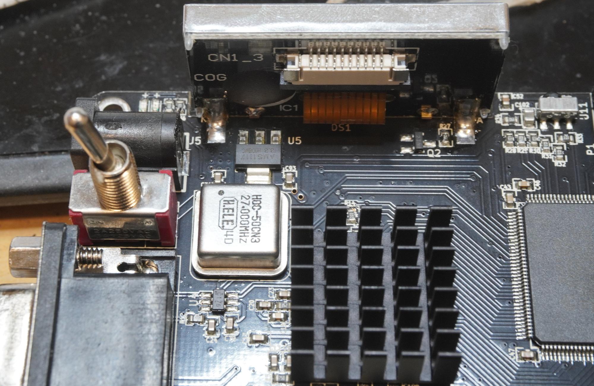
Thanks for the tip. The oscillator is fine. All the regulators seem fine except U6
u5 3.3V # the ground pin is not the middle one like you said here https://videogameperfection.com/forums/topic/ossc-1-5-trouble/
u6 0.12V # the output pin has a ~1 ohm resistance to ground. Some kind of short?
u7 1.9
u9 1.8u12 1.2
u13 2.5
u14 1.2
u15 1.8
u16 1.8What could that mean?
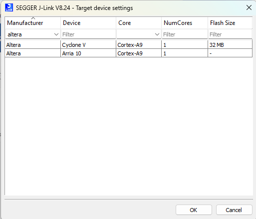
Pretty disappointing. I thought J-Link supported everything. Apparently not, or Altera decided to use some proprietary debug protocol built on top of JTAG. I’ve found a used Terasic probe on eBay, so will use that.
It would be a shame if the problem is not corrupt firmware. I don’t see how it can get corrupted. I did leave OSSC always on.
-
This reply was modified 3 months, 1 week ago by
spacesaver.
OK, I found the mapping. https://www.segger.com/products/debug-probes/j-link/accessories/adapters/intel-fpga-adapter. What wasn’t clear earlier is TRGNCE & TRGNCSO.
But apparently, the JLink 9.3 I have doesn’t support Cyclone IV.
Connecting to J-Link via USB…O.K.
Firmware: J-Link V9 compiled May 7 2021 16:26:12
Hardware version: V9.30
J-Link uptime (since boot): N/A (Not supported by this model)
S/N: 269305968
License(s): FlashBP, GDB
OEM: SEGGER-EDU
VTref=2.534VType “connect” to establish a target connection, ‘?’ for help
J-Link>connect
Please specify device / core. <Default>: CORTEX-A9
Type ‘?’ for selection dialog
Device>?
Please specify target interface:
J) JTAG (Default)
S) SWD
T) cJTAG
TIF>J
Device position in JTAG chain (IRPre,DRPre) <Default>: -1,-1 => Auto-detect
JTAGConf>
Specify target interface speed [kHz]. <Default>: 4000 kHz
Speed>1000 khz
Device “CYCLONE V” selected.Connecting to target via JTAG
ConfigTargetSettings() start
ConfigTargetSettings() end – Took 9us
TotalIRLen = 10, IRPrint = 0x0155
JTAG chain detection found 1 devices:
#0 Id: 0x020F20DD, IRLen: 10, Unknown device
Connect failed. Resetting via Reset pin and trying again.
ConfigTargetSettings() start
ConfigTargetSettings() end – Took 4us
TotalIRLen = 10, IRPrint = 0x0155
JTAG chain detection found 1 devices:
#0 Id: 0x020F20DD, IRLen: 10, Unknown device****** Error: CPU-TAP not found in JTAG chain
Error occurred: Could not connect to the target device
-
This reply was modified 3 months, 1 week ago by
-
AuthorPosts