VIC-II Kawari for C64
€74.95
€74.95 incl. VAT
VAT inclusive price is estimated based on the geolocation of your browser and may be subject to recalculation at checkout. What's VAT?
VideoGamePerfection.com are proud to be the official distributors for this excellent product. All boards are 100% genuine and purchased from the creator.
What is VIC-II Kawari?
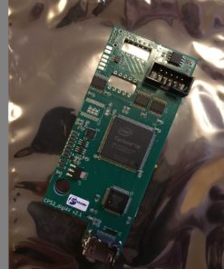
VIC-II Kawari is a hardware replacement for the VIC-II (Video Interface Chip II) found in Commodore 64 home computers. In addition to being compatible with the original VIC-II 6567/6569 chips, some extra features are also available.
The PCB interfaces with a real C64 address and data bus through the VIC-II socket on the C64 motherboard. The board can replace all the functions of a real VIC-II chip including DRAM refresh, light pen interrupts (real CRT only), PHI2 clock source for the CPU and, of course, video output. It’s ideal for resurrecting a C64 with a faulty VIC-II chip, or for adding better image quality to the C64 or more flexible video output options. Please read the entire page below before you decide if this product is for you.
Features
- Accurately reproduces VIC-II graphics functions
- Can replace VIC-II 6567/6569 in bread bin models
- No VSP bug
- S/LUM + Chroma output
- Configurable colour palette (for preference and programming)
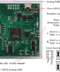
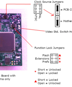
- Easily switch between PAL and NTSC video standards (software or hardware switch, our boards come pre-set to PAL)
- Four chip models supported (6567R56A, 6567R8, 6569R1, 6569R3)
- Can bypass broken clock circuits
- Eliminates white line on composite/s-video upscalers
- DVI (via micro-HDMI connector) and analog RGB (large board only)
- 64K of additional video RAM
- New graphics capabilities* (80 cols, hi-res, math, blitter and more…)
- Can be flash updated with new firmware
* Please note that new software is required to take advantage of the enhancements VIC-II Kawari has to offer and these features are included for entertainment/educational purposes.
Compatible motherboard Revisions
• Suitable for 250407, 326298, 250425 & KU-14194HB* motherboards (all “breadbin” and some C64C revisions, see note below).
NOTE: For 250425 boards, the large RF shield that sits under the keyboard should be left out. For the other revisions, the cover of the RF shield enclosure must be removed.
All purchases come pre-installed with an extra socket to give the board enough height to clear motherboard components.
* Due to the narrow RF shield surrounding the VIC-II socket on this model, an additional socket may be required for the large model (not included).
VIC-II Kawari revisions
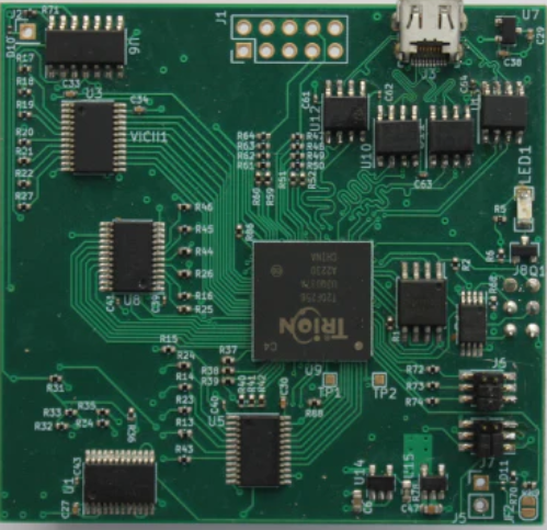
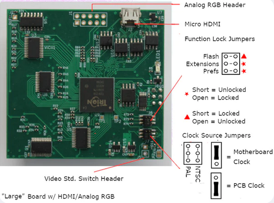
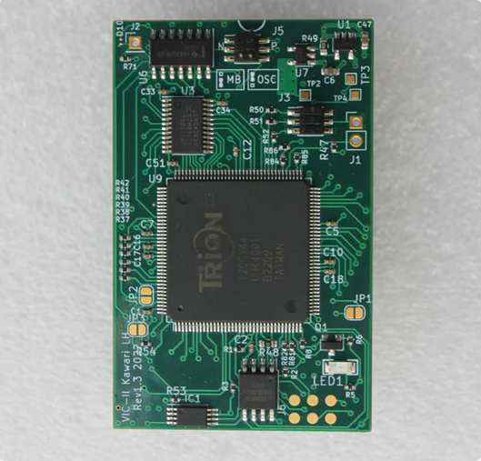
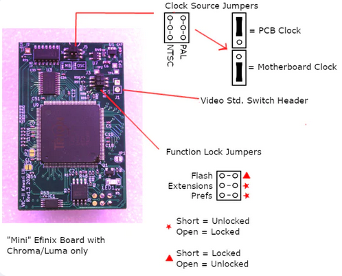
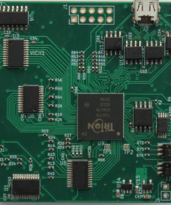
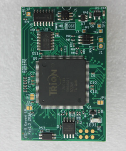
The VIC-II Kawari comes in two revisions. The mini board acts as a complete replacement for the VIC-II chip with the additional features listed above. The ‘large’ board also offers DVI and analogue video output options. Please be aware that the DVI output does not carry analogue audio.
Learn more about extra features on Mini/Large models
A configuration utility is provided which allows you to change the chip model at any time. Changes to the chip model will be reflected on the next cold boot. This means you can switch your C64 between NTSC and PAL-B with ease AND without opening up your machine!
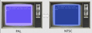
The full featured config utility takes longer to load, so a smaller quick switch program dedicated to changing the chip is also included. NOTE: You may optionally wire a hardware switch to the board which tells it to boot into the opposite standard than what was saved.
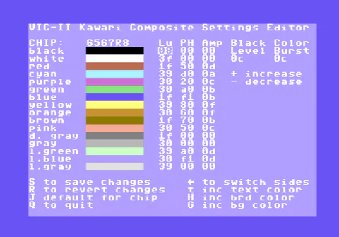
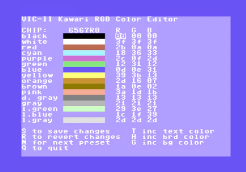
Your Commodore 64 will no longer be limited to 16 fixed colours! Each of the Commodore 64’s 16 colours can be changed for preference. For RGB based video (DVI/VGA), an 18-bit colour space is available (262144 colours). For composite (luma/chroma) video, a 18-bit HSV colour space is available (262144 colours). The colour palette can be saved and restored on a cold boot and is configurable for each chip separately.
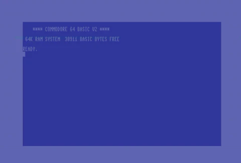
A true 16 colour 80 column text mode is available. This is NOT a soft-80 mode that uses bitmap graphics but rather a true text mode. Each character cell is a full 8×8 pixels. An 80 column text screen occupies 4k of Kawari video memory space (+4k character definition data). A small program (2k resident at $c800) can enable this for the basic programming environment. The basic text editor operates exactly as the 40 column mode does since the input/output routines are simply copies of the normal kernel routines compiled with new limits. This mode also takes advantage of hardware accelerated block copy/fill features of VIC-II Kawari so scrolling/clearing the text is fast.
NOTE: 40 column BASIC programs will not necessarily run without modification in the 80 column mode. If the program uses print statements exclusively, then there’s a good chance it will work. If it uses POKEs to screen memory, it will have to be modified.
NOTE: The 80 column display was not intended for TVs or low resolution monitors. The mode will function using a composite signal but the bandwidth is too low and you will not get a sharp display. You may get a more usable image using a custom s-video cable (and possibly an upscaler).
New high resolution video modes
VIC-II Kawari adds some new video modes for the 8-bit enthusiast to play around with:
| 640×200 16 colours | Every 8×8 cell can be one of 16 foreground colours |
| 320×200 16 colours | Every pixel can be set to one of 16 colours |
| 640×200 4 colours | Every pixel can be set to one of 4 colours |
| 160×200 16 colours | Every pixel can be set to one of 16 colours |
Hardware DIV and MUL registers
Hardware divide and multiply registers were added to avoid costly loops. Some programs can be modified to take advantage of these registers.
Blitter/copy/fill
A blitter is available to copy rectangular regions of memory quickly without using the CPU. There are also block copy and fill routines that can move or fill video ram. These features are useful for the new hi-res modes.
White line killer
VIC-II Kawari lets you remove the annoying white line on the left side of the screen that will show up on upscalers like the RetroTink.
Analogue RGB header with optional 15khz mode (large board)
The large model comes with an unpopulated analogue RGB header that can be used to connect to a VGA or 1084 monitor. A 15khz mode is available and C-SYNC option is also available for some 1084 monitors that require it.
Pure digital signal (DVI) (large board)
The large model includes a micro-HDMI connector for a pixel perfect picture on HDMI displays.
Limitations (please read)
- May not work on older monitors or TVs (non-standard resolutions)
- You won’t get a 4:3 aspect ratio unless your display has the option
- You may have to turn off the display or use an HDMI switch to boot the C64 or reset changed colours/new hi-res modes
- Using the motherboard oscillator may result in loss of sync
DVI limitations details
-
The resolution/timing the board outputs is not a standard resolution. Some older TVs/monitors may not sync to it. Some HD capture cards only accept standard resolutions as well (like 720p or 1080p) and will also not sync.
-
The display will be horizontally stretched on most HDMI displays. You will not be able to get a perfect 4:3 aspect ratio. Some displays have an aspect ratio option that can yield a better result. There are no plans to do any processing on the output (i.e. scaling).
-
HDMI monitors can power the FPGA core through the HDMI cable. This prevents the core from booting properly (or sometimes booting at all). It’s an unwanted side-effect of driving the TMDS lines directly from the FPGA core. This device is not an HDMI device, it is DVI over an HDMI connector. A buffer IC is required to avoid this but would add more cost to the board. The work around is to either power off the monitor or use an HDMI switch.
-
The quality of the motherboard clock is not sufficient to derive the 40x dot clock required for the DVI signals. It appears the high jitter on the crystal is the cause. The motherboard clock was never meant to go through a clock multiplier to high frequencies. This appears to cause sync loss especially on NTSC boards. For this reason, the on-board oscillators should be used to drive the digital display modes.
Soft reset + hi-res modes / colour registers
Please note that if you change colour registers or enable hi-res modes, Kawari will not revert back to the default palette or lo-res modes with a soft reset (or even RUN/STOP restore). If you want the Kawari large model to detect soft resets, you can connect the through hole pad labelled RST in the upper left corner of the board to the 6510’s RESET pin (or any other RESET location) using a jumper wire and grabber.
Cartridges that use DOT clock pin (pin 6)
A cartridge that uses the DOT clock signal on pin 6 may not work when the clock source is set to the on-board oscillator. The signal that reaches pin 6 of the cartridge port comes from the motherboard clock circuit and will likely be out of phase/sync with the clock generated by the on-board oscillator. In this case, you can configure your Kawari to use the motherboard’s ‘native’ clock instead of the on-board oscillator. Note, however, that only the machine’s ‘native’ video standard will work with such a cartridge. Since the vast majority of cartridges do not use pin 6, this should not be a problem for most users.
Turn off Pi1541 GraphIEC feature
The Pi1541 has a feature that displays the IEC bus information to its display. This can interfere with tight timing requirements on some demo fast loaders (even on a genuine VIC-II chip) and can lead to corrupted data loaded into memory. If you are experiencing random crashes on demos like ‘Uncensored’, ‘Edge of Disgrace’ or similar demos, this is likely the cause. It is recommended you turn this feature off by adding ‘GraphIEC = 0’ to your options.txt.
Create Something New!
VIC-II Kawari represents an opportunity for 8-bit enthusiasts to create new applications for an enhanced C64 graphics chip. All new registers/features are fully documented at the github project site.
installation
Installation Instructions
Installation is easy and requires no soldering and can be completed with these simple steps:-
1) Disconnect all cables from your C64.
2) Open your C64, there is no need to disconnect the keyboard, though be sure to rest the top of the case against something so as not to strain the keyboard wire.
3) Locate the VIC-II chip and using an EEPROM remover or a small, flat headed jewellers screwdriver, remove the chip and store it away safely (especially if it is still working!). Any add-on boards which interface directly with the VIC-II, such as LumaFix, should be removed as they are no longer needed. Use of a S-video bypass board is still recommended for best picture quality however.
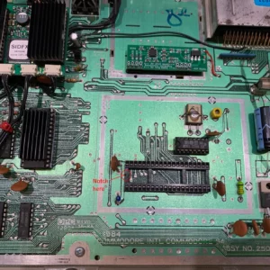
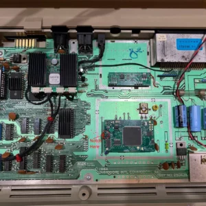
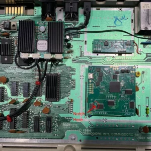
4) Locate the notch on the end of the VIC-II socket and line it up with the notch on the VIC-II Kawari board. Ensure the pins on the bottom of the board align correctly with the socket holes in your C64, then press down gently but firmly. See the pictures below for an illustration (click or tap to enlarge them).
5) Before closing the machine, reconnect the power cable and turn on the C64. Ensure that a red LED glows on the VIC-II Kawari board. If it does not, immediately power the C64 off again and check that the board is correctly oriented and fully inserted into the socket.
6) Close your C64 back up again, reconnect all cables and enjoy the VIC-II Kawari!
Special installation instructions for large board (Re: DVI/RGB)
As mentioned above, the large model includes a micro-HDMI connector and analogue RGB header. To fully take advantage of its digital or analogue output capabilities, the RF shield and/or RF modulator should be removed. Otherwise, plugging in the micro-HDMI cable is not possible even with the extra socket provided (the shield, if present, is in the way). Also, removing the RF modulator provides an exit port for the cable. Strain relief on cables as they exit the machine is important and is the responsibility of the user. If you are building a new C64, you can use a VIC-II Kawari and leave the RF modulator unpopulated. VIC-II Kawari is also fully compatible with our S-Video Bypass/RF Replacement boards.
Demos and configuration tools
For the palette editor, configuration tool and demos, click or tap here.
Related
| Weight | 100 g |
|---|---|
| Dimensions | 6 × 11 × 16 cm |
| Country of Origin | CAN |
| hscode | 9504500000 |
| Customs Description | Component for videogame |
| Board Type | Mini, Large |
2 reviews for VIC-II Kawari for C64
Add a review Cancel reply
Related products
Mod kits and spare parts
€17.00
€17.00 incl. VAT€169.40
€169.40 incl. VATMod kits and spare parts
€11.00
€11.00 incl. VATMod kits and spare parts
€13.30
€13.30 incl. VATMod kits and spare parts
€16.00
€16.00 incl. VATMod kits and spare parts
€9.15
€9.15 incl. VATMod kits and spare parts
€25.35
€25.35 incl. VATMod kits and spare parts
€76.50
€76.50 incl. VAT


eightbit –
Absolutely amazing device. Randy has created a work of art here, and VGP delivers the goods as always. I purchased both the mini and the large and they are both fantastic devices. Buy one if they are available, you will NOT regret it!
Ben –
I got the Kawari large board delivered yesterday. I was really looking forward to it since I had to wait 2 months for the unit. After installing it in my Assy 250407 C64 board and connected it via a dvi-hdmi cable, I fired it up. Immediately I was blown away by the beautiful image quality. It was the same crisp quality I was getting with my Raspberry Pi equipped BMC64. After playing around for a while I am convinced that this is the perfect video solution for my old C64. The only thing I noticed is that the onboard Trion chip gets very warm. I will put a heatsink on it.