Morpheus_79
Forum Replies Created
-
AuthorPosts
-
I’ll check the suppliers you recommended, order everything (with a few extra spare AMS117), and let you know of my results.
Pay attention to buy a version of the AMS1117 which outputs fixed 3.3V (since there are also versions available for other fixed voltage outputs, like 1.8V… and a version with an adjustable output too -> which all won’t work).
Thanks a lot again Morpheus_79 for all your valuable and quick answers 🙂
You’re welcome.
So I’m assuming the problem is restricted to U5 only ?
If the shorts on U7, U9, U12, U13, U14 are U15 all gone (on the rows with the three pins: only the middle pin should be connected to ground), then only U5 was faulty.
Maybe they changed the U5 for costs reasons or because it would no longer be produced in a near future ?
It’s still available and will be produced in the near future. But it’s harder to get from local suppliers in some countries. There are some very similar voltage regulator from smaller Chinese manufacturers (AIC1221-33GY3TR… MIC37100-3.3WS) with the same package size and pinout as the AP7361C:
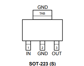
I can understand using the AMS1117… since it is VERY common and readily available in most countries… BUT (as you’ve said) it has a pretty different pinout though:
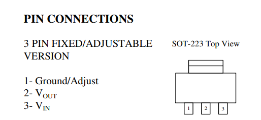
So in the end it probably was cheaper to change the pcb layout and use an AMS1117, since their cheapest versions go for around 3 Cents per part, while the AP7361C and its suitable replacements cost around 6-8 times that price.
Interesting -> your OSSC layout differs a bit from the official 1.6 layout… which can be found on marqs github:
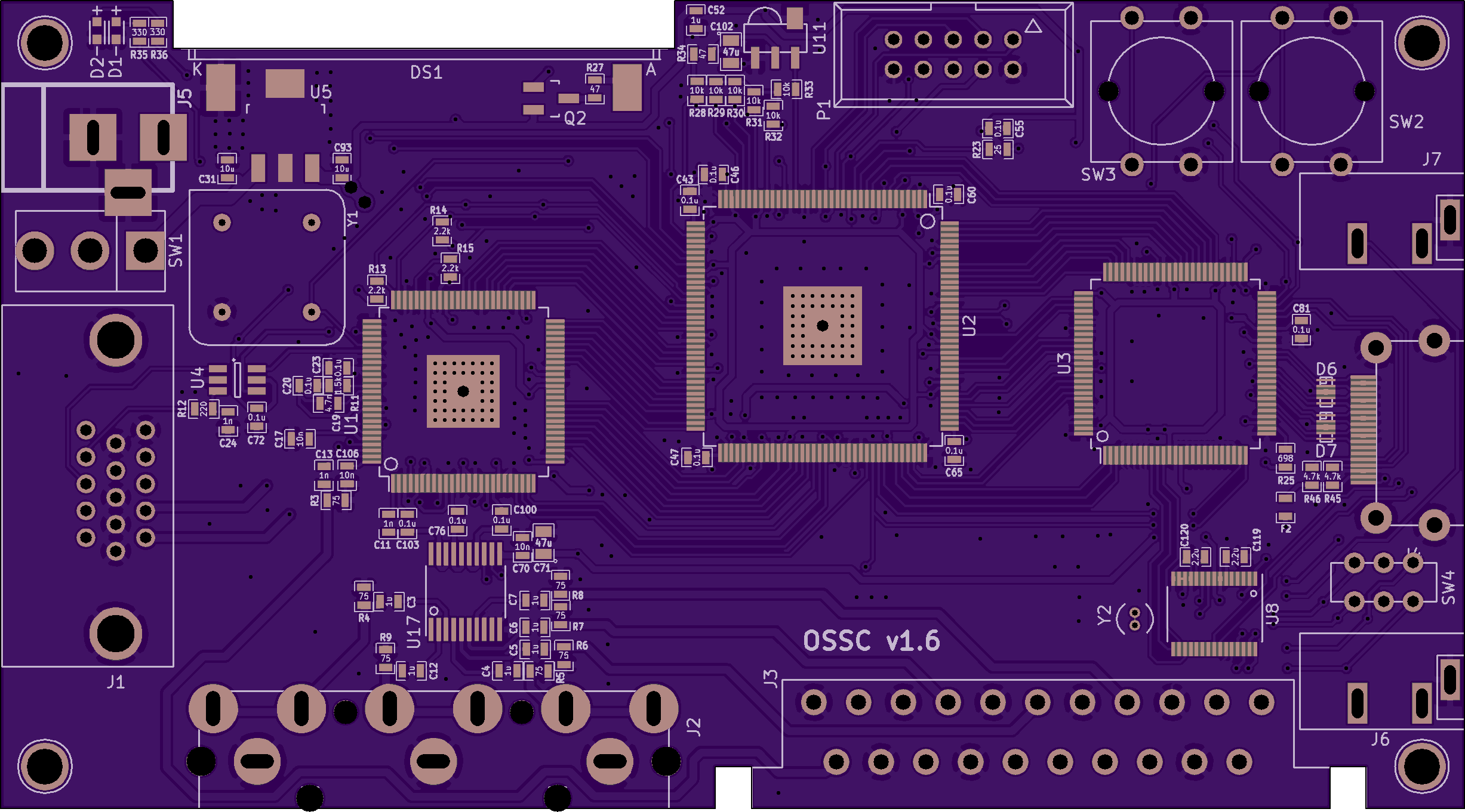
That could be problematic for finding a replacement part. Because i don’t know for sure, if for U5 the part from the official BOM was used. It is probably a different voltage regulator with a different pinout. I assume this, because:
- Your U5 is upside down, but the filter capacitors for the input and output voltages (= C31 and C93) haven’t switched places -> there must be a reason for it.
- Your U5 probably isn’t a AP7361C, since if it were, its 5V input would be connected to ground. But: that’s not the case for you, because it’s clearly visible in your pictures that the 5V input is connected to the outer of the three pins on U6, which are NOT connected to ground.
Switched input/output-pins for your U5 means: not the 5V input is shorted to ground, but its 3.3V output. Which would make sense: the input pins of your U7, U9, U12, U13, U14, U15 were all shorted to ground on your OSSC, which are all connected to the 3.3V output line of U5.
In conclusion: your OSSC uses a voltage regulator for U5, where (compared to an AP7361C) the input and output pins are switched. Which means: you can’t replace your U5 with an AP7361C, since it has the wrong pinout for your unofficial/modified OSSC! So: DON’T BUY AN AP7361C AND PUT IT IN! You would fry it!
Now for the more problematic part: what’s written on your U5? Since it is not a AP7361C, the markings may help to find a suitable replacement…
Would anybody have recommendation for another reliable supplier for Europe ?
For Europe i would recommend lcsc.com, tme.eu or rs-online.com. All provide reasonable shipping costs and have European warehouses or ship from/over European countries. While lcsc.com has the biggest selection of components, it’s the slowest for shipment, since it’s based in China.
-
This reply was modified 1 year, 4 months ago by
Morpheus_79.
I also noticed that my U5 has no heatsink, and that it gets burning hot. Could it be that letting the OSSC ON during several days without heating caused some melting or short inside it ?
U5 doesn’t need a heatsink and shouldn’t get extremely hot. While it’s probably not recommended to run the OSSC for days and days and days, there should nothing get “melted” together or fail because of extreme heat produced. The A/D converter IC (U1) is the only one getting pretty hot – therefore its heatsink.
More detailed informations are needed. On U5: the big pin on one side and the middle pin on the side with the three pins are connected to ground? Is that correct??
Which regulators on the bottom side of the pcb have a short to ground (U?)? Please take a photo and mark their pins connected to ground!
Do you think that this short circuit is internal to a regulator (and that I should try to replace it), or might it be located elsewhere ?
For each regulator the input and output are each connected with a capacitor, which is connected to ground. So it could be a failed capacitor… or the regulator itself.
The OSSC should work without D5… but removing D5 and shorting the fuse isn’t a good idea, because:
D5 is TVS diode that clamps voltage to 5V (in reality effective clamping voltage is a bit higher and depends on current), protecting from surges and overvoltage. When continuous overvoltage (or negative voltage with more than ~0.6V amplitude) is applied, it burns into a short circuit so that downstream devices are still protected. That eventually triggers overcurrent protection (e.g. fuse) if such is present. The diode and fuse are placed before power switch, so if you hadn’t power turned on yet, then you almost certainly did not damage anything but the diode.
If one or both are broken, than it’s for a reason. Circumventing both may damage your OSSC further.
If U5 gets very hot, you should check for shorts like described here:
https://github.com/marqs85/ossc_pcb/blob/v1.6/assembly/assembly_tips.txt
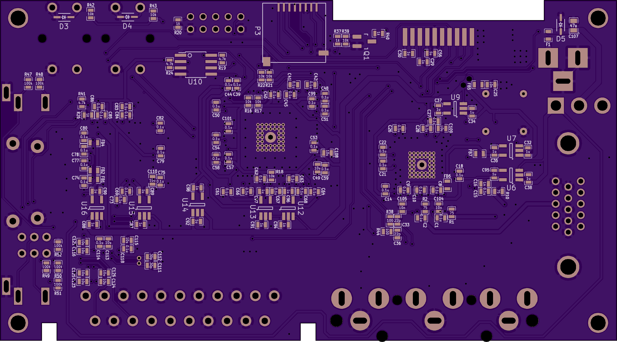
It’s a good idea to check that power supply lines are not shorted to ground. It can be done easiest by checking all the regulators:
-on bottom side, there are 8 small regulators in SOT-23-5 packages (U6, U7 etc.). Verify with a continuity meter that only the middle pin on the side with 3 legs is connected to ground
-on top side, there is one larger regulator (U5) behind the display. Verify that only the middle pin (on the side with 3 pins) and the heatsink pin are connected to GND@Zacabeb Anyone can do that with enough practice and some decent soldering tools. And a microscope may help – especially if your eyesight is getting worse with age, like mine does 😉 .
@marqs Thanks for all the time you still put into this to improve everything!-
This reply was modified 1 year, 6 months ago by
So… if i rewire the connections between U1 and U2 on an OSSC 1.6 to match the connections on an OSSC 1.8:
- disconnect pin 127 of U2 from ground and connect ist with button 0 (together with pin 128)
- cut the trace to pin 22 of U1 and connect the trace with pin 25 instead
… the beta firmware should work too (while leaving the functionality of both LEDs intact)?
Seems like there’s a fault in the schematics for version 1.8 (or are there newer ones?):
https://github.com/marqs85/ossc_pcb/blob/v1.8/doc/ossc_board.pdf
According to those FPGA pins 127 & 128 are connected as a board revision indicator while in reality pins 126 and 128 need to be connected.
So i had to redo the rewiring of my v1.6 pcb:
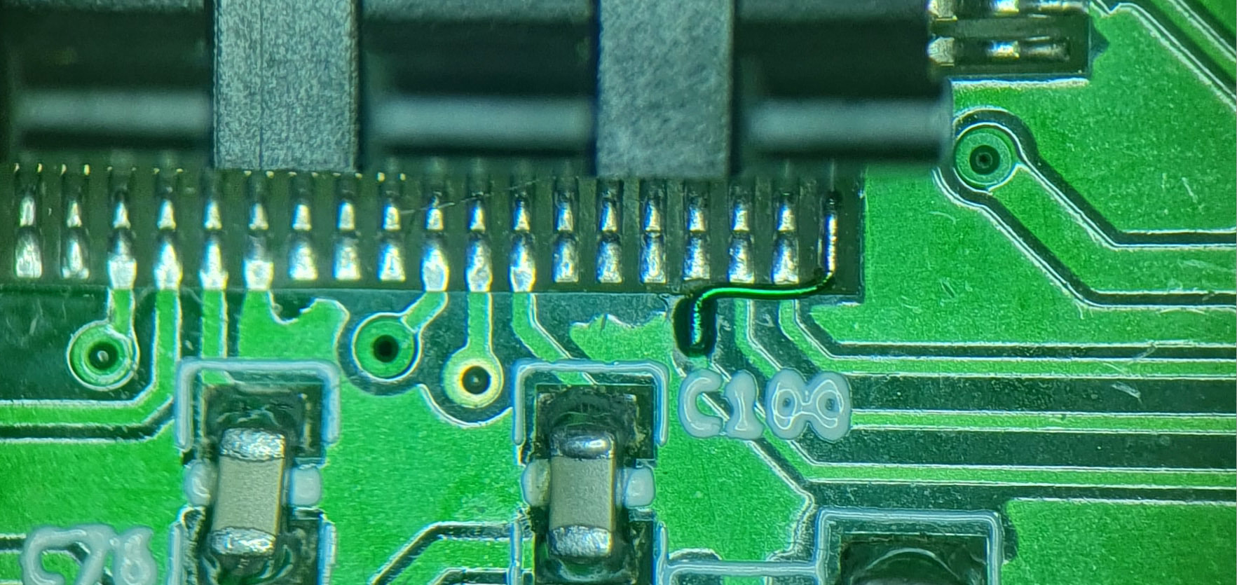
… but it works now!
All 1.xx branch firmware requires OSSC 1.8 or the hardware modification to an older OSSC as detailed on the first page.
So… if i rewire the connections between U1 and U2 on an OSSC 1.6 to match the connections on an OSSC 1.8:
- disconnect pin 127 of U2 from ground and connect ist with button 0 (together with pin 128)
- cut the trace to pin 22 of U1 and connect the trace with pin 25 instead
… the beta firmware should work too (while leaving the functionality of both LEDs intact)?
A broken chipset after 3 years and a few hours of utilisation ? What a mess…
As ‘marqs’ wrote: it’s very unlikely… and i’ve never seen a broken U8 in the past (if i remember correctly) – but it’s possible. Sadly a few hours of utilisation won’t protect you from electronic components failing sometimes.
Probably a broken U8 (PCM1862):
Texas Instruments PCM1862 Series Audio A/D Converter ICs – Mouser Germany
would it be possible to use pin 46 on the chip labelled EP4CE15E22 as a substitute for R35?
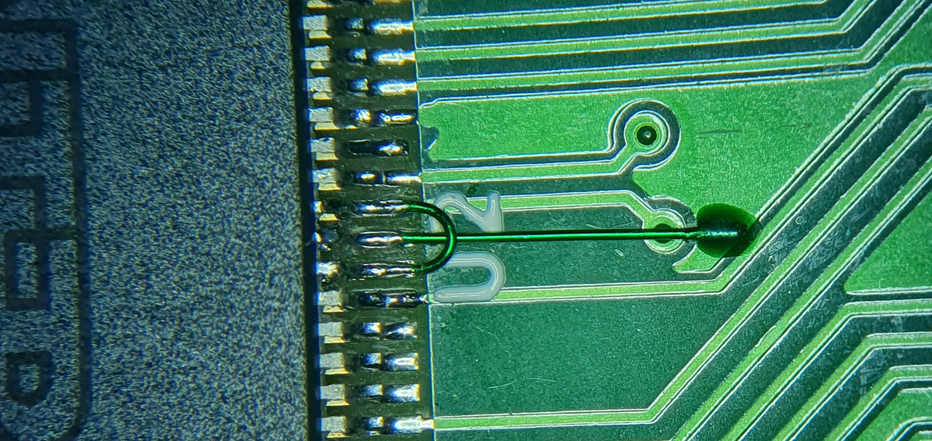
Yes… it is possible to remove R35 and then solder a thin enameled wire between pin 25 of U1 (TVP7002PZP) and pin 46 of U2 (EP4CE15E22 / Cyclone IV FPGA). It does basically the same as connecting pin 25 to the input pad of R35.
I did it and it worked flawlessly:

BUT soldering a wire to the pad of R35 is MUCH easier than soldering to pin 46 (especially if you had a hard time soldering to the pad of R35 in the first place). Accidentally shorting some pins on U2 could potentially damage the FPGA and therefore render the whole OSSC useless!
-
This reply was modified 1 year, 8 months ago by
-
This reply was modified 1 year, 8 months ago by
-
This reply was modified 1 year, 8 months ago by
You just need a remote which makes the LED of the OSSC flash. That means, the remote uses the NEC IR protocol. It is pretty common – i’ve had 3 remotes lying around (from a Toshiba TV, an LG TV and from an old DVB card) using this IR protocol.
You probably won’t find a remote, which uses the exactly same IR code for one of its buttons as your original L336 uses for its menu button.
But that is not a problem after all, since you can set your OSSC to use another IR code for its menu -> power your OSSC on while holding BTN1… as described here:https://junkerhq.net/xrgb/index.php/OSSC#Remote_control_setup
That way you can setup your OSSC using any remote it recognizes.
So simply find a remote your OSSC recognizes (flashing green LED on your OSSC), use any button of this remote (which is recognized but doesn’t do anything on your OSSC) to program the menu button on your clone L336 (and another one for the up arrow button) and then start your OSSC with a pushed down BTN1, to make your OSSC re-learn every button of your clone L336.
This should work fine… until you flash a new OSSC firmware. After that you have to redo the last step since your OSSC resets to the default IR codes after a firmware update.
I’ve had several clone remotes in the past. All came with a printed instruction – the same as the original Chunghop manual from here:
http://en.chunghop.com/productDetail?id=541
But on all of them the button combination for one key learning never worked. No matter how long i pressed the buttons – it didn’t do anything.
Later i bought two original remotes and tried it again. With them pressing the device and channel up/down buttons the same time made them enter learning transmitting/receiving state and i was able to copy one remote setup to another remote.That’s how i know. The clones are still viable remotes and work perfectly fine aside from that.
Real Chunghop L336 remotes support one key learning, to copy the whole setup from one L336 to another L336.
But there are a lot of L336 clones around, which do not support one key learning. Maybe your first remote was a clone… maybe your new one is… maybe both are clones. But if copying the key setup from one L336 to another won’t work, at least one of them is a fake one (most clone remotes don’t have ‘CHUNGHOP L336’ written on them… only ‘L336’).
You can still use the normal key-by-key learning with those fake L336. But then you’ll still stuck with the non-working menu button. So i would still recommend finding an old TV/DVD/BD/Receiver remote with OSSC compatible IR codes and use at least one its buttons as source for the menu button on your new L336.
This won’t work, since a brand new L336 is empty/blank. The L336 needs to be programmed with the compatible IR codes of the NEC IR protocol. You can use an old TV or receiver remote your OSSC recognizes to program your L336 (some Toshiba or Philips ones may work). Or you can use an (USB) IR transmitter with LIRC/WinLIRC. There are even some older smartphones with integrated IR transmitters, which can be uses as remote replacements or to program your blank L336.
-
AuthorPosts