Nintendo 64 RGB Bypass Amp (Revision 1.2b)
€16.90
€20.11 incl. VAT
VAT inclusive price is estimated based on the geolocation of your browser and may be subject to recalculation at checkout. What's VAT?
34 in stock
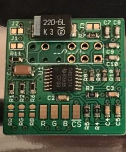
The Nintendo 64 RGB Bypass Amp is a professionally made RGB amplifier for early model Nintendo 64 consoles. The part is ideal if you want to RGB modify your N64 console and you have determined that it is compatible with the “Basic” RGB amp mod, as discussed on RetroRGB’s website here.
Our newest revision of the amp includes several improvements:-
- Uses the THS7374 amplifier, which can generate a sharper image
- User selectable low-pass filter
- Optional buffered CSYNC (clean composite sync)
- New – User selectable CSYNC output, choose between 75ohm or TTL.
Instructions for use
Please follow the installation guide as provided by RetroRGB.com here. The guide assumes some familiarity with the internals of the N64 console.
Key points:
These key points have been updated for revision 1.2b, If you have an older revision of the Nintendo 64 RGB Bypass Amp, click here. The version number of the amp is printed on the back of the PCB.
1. This amp has been configured for use with a SNES NTSC cable. Please use a properly wired RGB SCART cable designed for an NTSC Super Nintendo/Super Famicom console.
2. It is important that you isolate the back side of the RGB amp PCB with insulation tape and that you also isolate the two metal tabs on the N64 shielding that sit directly above the RGB amp PCB. It may be best to cut these metal tabs off if possible, as shown in the photo below, if not then the tab above the bottom of the RGB amp should be bent upwards and flat to allow access for the wires and the tab above the right side of the RGB amp should at the very least be covered with insulation tape.
3. R, G and B pads can be connected to the bottom side of C124, C125 and C126 respectively.
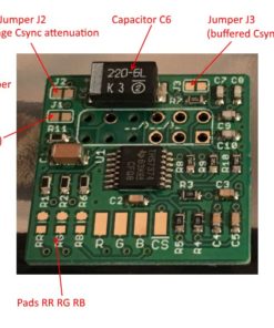
4. If you wish to use the buffered Csync on the RGB amp then you will need to solder bridge jumper “J3”. If installing into a NUS-CPU-03 system, ensure that pin 3 of the MultiAV is freed before starting the installation. You can do this by removing components from the N64 main board as follows:
- remove R14 and C22
- optionally remove also Q1, R1, R15 and R16
If installing into a NUS-CPU-04 system then the above components should not be present.
Once any necessary components are removed you can connect the CS pad of the RGB amp to the top pad of R16 or the via directly above.
5. If your device doesn’t work well with the buffered Csync on the RGB amp you can try bypassing capacitor C6. The bypass jumper for this purpose (previously known as “J2”) has now been moved back to it’s original location beneath the capacitor so you will need to remove the capacitor to close the jumper. The jumper marked “J2” on the v1.2a PCBs is now used for another purpose and should not be confused with this one.
6. This board has been configured to output 75ohm terminated Csync with either a straight through connection or a 470ohm attenuated connection. The PCB is configured for a straight through connection by default (in other words, it outputs properly attenuated 75ohm Csync), so If your SCART cable does not have a 470ohm attenuation resistor installed then you will not need to change anything.
If your SCART cable has a 470 ohm attenuated connection (attenuation resistor installed), then you will need to solder jumper “J2” to get the correct voltage level for 75ohm Csync. It is strongly advised not to solder jumper “J2” unless you definitely know that your cable has a 470hm resistor installed on the Csync connection otherwise you may possibly damage your equipment.
If you need a new Csync cable to use with your modified console, you can use the NTSC SNES PackAPunch cable available here. Choose either the “CSYNC TTL 2.5 Volt” option (and leave J2 open) or Csync 470ohm option (and solder J2 closed) when purchasing the cable.
7. Jumper “J1” is for the low pass filter.
- Leave J1 open: internal filter of EACH channel is NOT bypassed (low pass filter is ON).
- Close J1: internal filter of EACH channel is bypassed (low pass filter is OFF).
Please note these parts are intricate and require soldering skills to fit. We cannot provide technical support with fitting, if you require a professional fitting service see our console mods section. While we cannot offer technical support for DIY installations/parts, community based support for our mods is available in the forum here.
Based on an open source design by Borti4938. Interested in building your own? Check out the Github page here.
Related
| Weight | 15 g |
|---|---|
| Country of Origin | CN |
| hscode | 9504500000 |
| Customs Description | Component for videogame |
1 review for Nintendo 64 RGB Bypass Amp (Revision 1.2b)
Add a review Cancel reply
Related products
Mod kits and spare parts
€45.00
€53.55 incl. VAT€60.00
€71.40 incl. VATComputer
€89.43
€106.42 incl. VATMod kits and spare parts
€16.90
€20.11 incl. VATMod kits and spare parts
€30.00
€35.70 incl. VATMod kits and spare parts
€15.95
€18.98 incl. VATMod kits and spare parts
€15.00
€17.85 incl. VATMod kits and spare parts
€19.15
€22.79 incl. VAT





Levente –
Works perfectly with a french N64 (NUS-001 FRA)!
Connected RGB from the amp to R8, R9, R10 on the N64 board and CSYNC directly to pin 14 on the VDC NUS chip. Did not desolder any other components from the N64 board.
Thanks.
VDC NUS
pin 14 CSYNC (SRGB pin 7)
pin 17 RED
pin 19 GREEN
pin 21 BLUE